KIWI Mk2
I/C ENGINE BUILD
Part 15 By Vince Cutajar

KIWI Mk2
I/C ENGINE BUILD
Part 15 By Vince Cutajar

Started work on the piston casting and trued up as much as possible the ID of the skirt. Took some skimming cuts on the ID to clean it up as much as possible. Ended up about 0.2mm wider than the plans and still did not clean it up fully. I then worked on the OD of the piston and left it a little oversize on purpose. After that I reduced the length of the skirt to size. I then eyeballed the bosses horizontal as much as possible. Then, using the height gauge I had locked on the centre height of the lathe, I scribed two horizontal lines, one on each side of the piston.


To increase the distance between the wrist pin bosses, put the piston and clamped it in the vice and trued it up parallel to the mill table. Using a long series 6mm end mill I milled the bosses to get a 9/16" distance between them.


I then located the mark for the hole with a wobbler and centre drilled and drilled 5.5 mm the first hole. I then passed the centre drill through the same hole to mark the boss on the other side. Drilled again 5.5 mm and then reamed both holes 6mm.


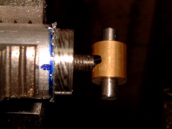
Photos show the mandrel and the piston on the mandrel.

A trial fit of the piston in the cylinder with the cylinder fitted to only half of crankcase to see if the conrod clears the surrounding metal. Also I wanted to see how far up the piston goes in the cylinder. I was a bit disappointed because it should be flush with the cylinder liner lip but instead it was sitting 1.2mm lower. While I was fussing about how to get the piston higher it dawned on me that I had on purpose left the platform of the cylinder about 1mm higher than required to reduce the compression. Westbury had suggested this for an easier starting and more docile engine.