
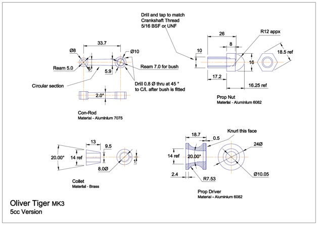
(Click on drawings to download - for personal use only.)

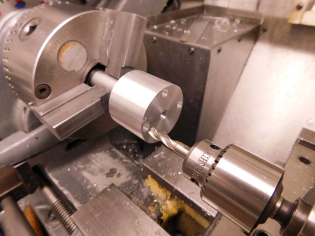
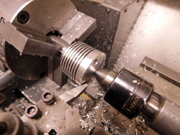
The issue of whether to drill the bolt holes before or after machining the fins was settled some time back. I prefer to drill the holes first as, though this does give interrupted cuts as the holes are passed by the tool, the burrs are thrown into the holes rather than into the fin gaps. De-burring is then a simple matter of running the drill back through to clear the burrs. The holes are drilled through in two stages to limit run out and simply counterbored using an FC3 cutter.
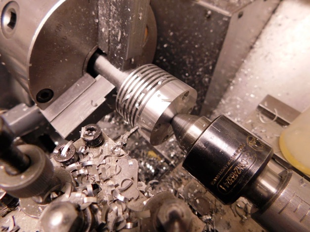
The tool for cutting the fins was just a piece of HSS ground on the off-hand grinder to give the required 1.4mm gap. It cut the 6mm deep slots along with the interrupted cuts where it passed the holes without any pick up issues mainly due, I'm sure, to using lots of paraffin lube.
The tops were shaped by a series of flats formed by shaving on the side of this 'favourite tool' - when it comes to grinding tools I'm the most idle of machinists and will just keep tweaking the ends of previously ground tools until little is left save the very tip (which is fundamentally the only part that does the work anyway) This is one that seems to survive that process and retains its shape for the long term for some reason.
The tops were then finished by gentle filing followed by emery, then wet and dry and finally a smoothing with a GarryFlex block and a polish with fine ScotchBrite.
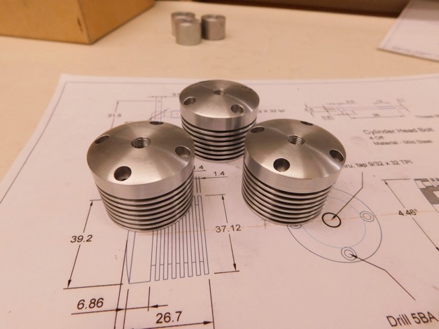
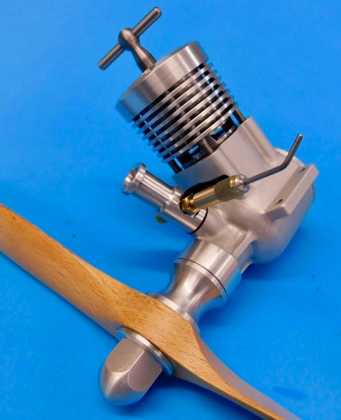
Finished ready to fit.

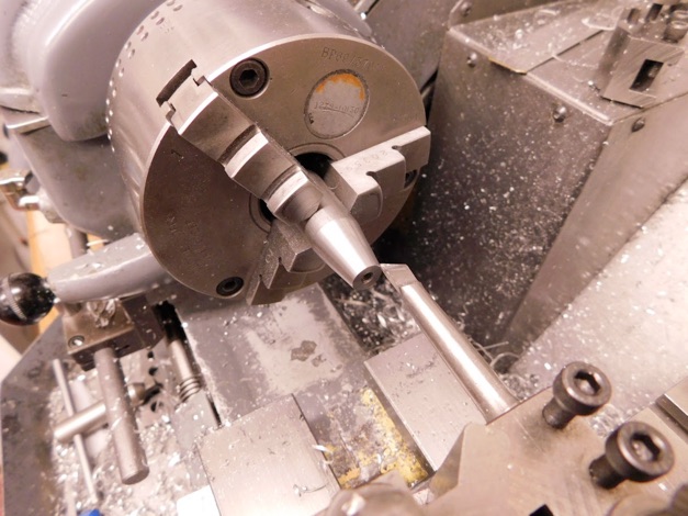
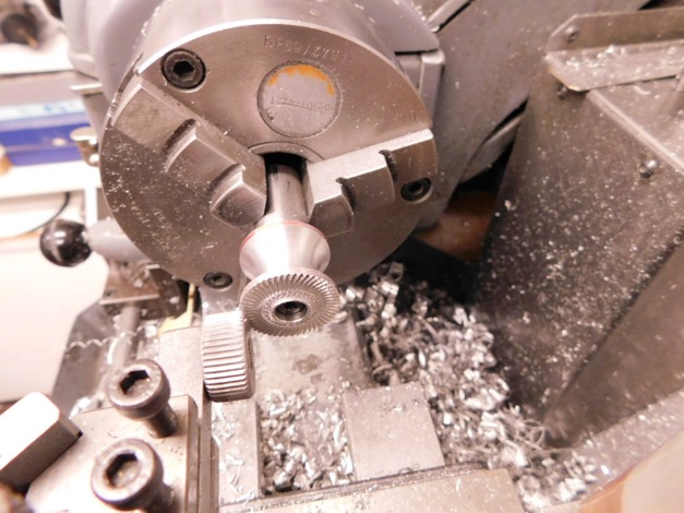
The blanks were held on the mandrel by a 4BA screw and a form tool used to form the profile. This was just ground free hand - nothing exact, radius wise - and cut well from start to finish.

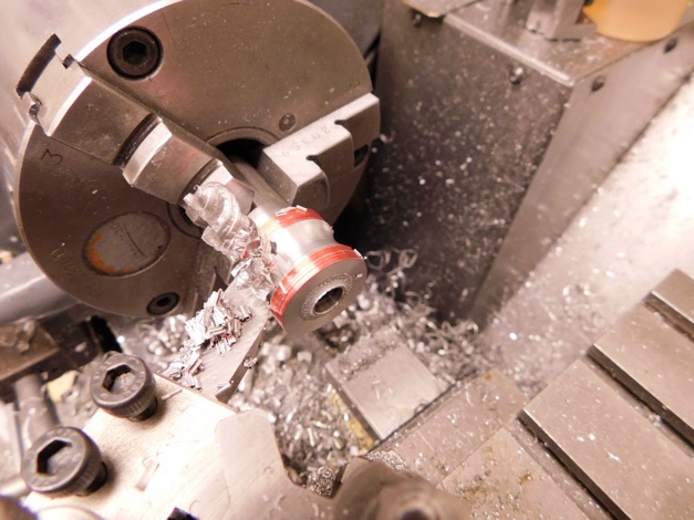
The knurling was done in the usual fashion - lathe run in reverse (keeps the knurl against its holder) and slowly moved in toward the centre (note the knurled washer on the over run ). Big problem for me is that I don't have flood coolant and this is one job that would really benefit from it. Its just a matter of taking things slowly and trying to keep the wheel clean with a small wire brush.
The venturi were simple turning jobs as were the prop nuts so here's how the parts made so far look. Colour coding the venturi ensures that the cross hole matches the thread pull up. The back plates, made some time back, are in the safest place to prevent any minor damage to the threads - liberally coated with anti gall grease and temporarily nipped up home in their cases.


Part one here. Part two. Part three. Part four. Part five. Part six. Part seven