Stand construction.
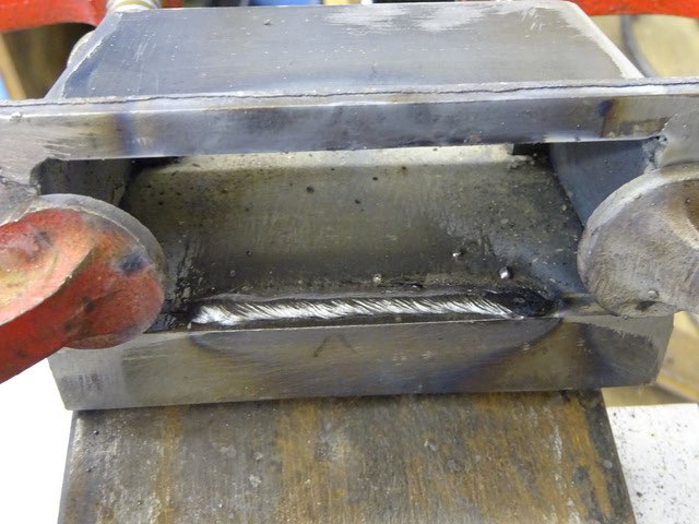
Four off-cuts of steel were welded together to form the bottom plate.
The four sides welded up into a box, they actually taper inwards towards the top despite what it looks like in the photo.
Bottom plate welded to the sides internally to make clean up easier.
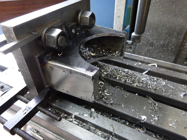
Cutting the curve to clear the crankcase with a boring head.
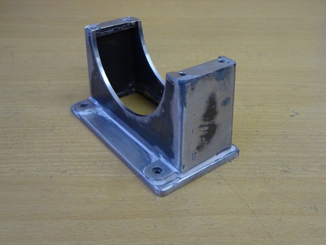
Fettled & filled ready for paint.
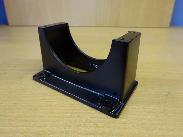
Primed, satin black and satin fuel proofed.
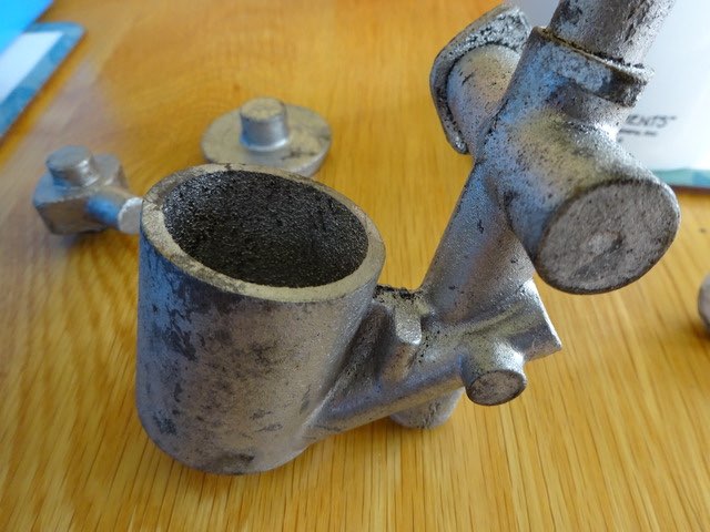
Time to tackle the carb, on the model this comes as a main aluminium casting together with a lid for the float chamber and top for the oil feed. Don't look too bad castings on this example.
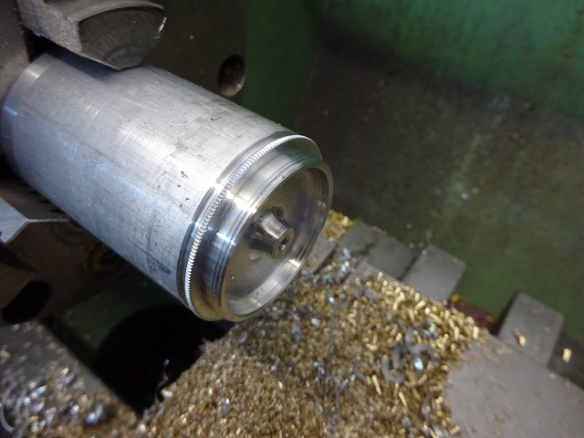
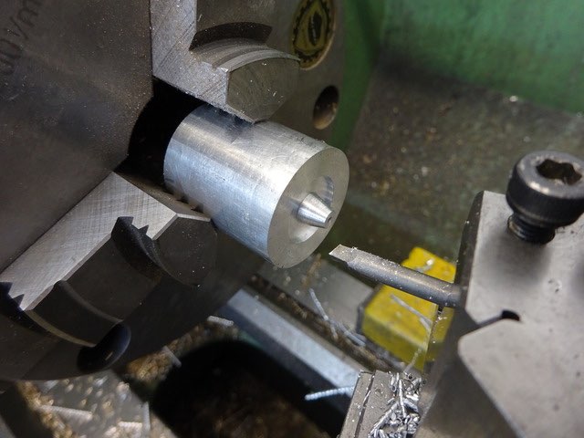
I turned the bottom of the lid first and cut the thread, then parted it off and set aside.
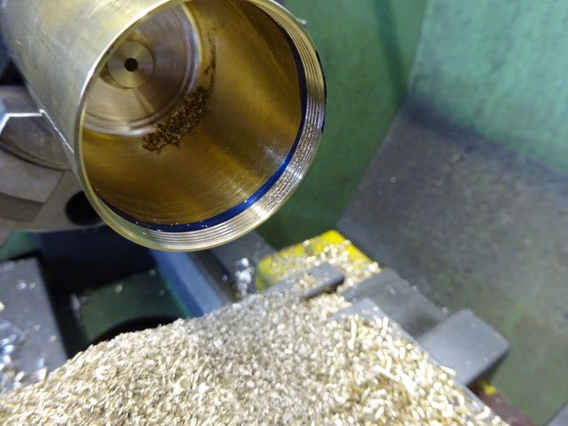
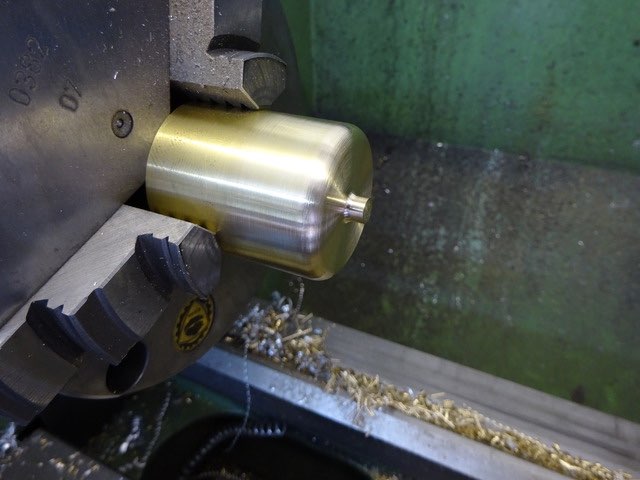
I decided to fabricate the ‘casting’ from brass, as my engine won't be going into a boat or car there is no real need to worry about the weight. So starting with some 1.5" brass this was reduced to a large pile of swarf leaving a float chamber that was then threaded to take the lid while the change gears were set up from doing the lid.
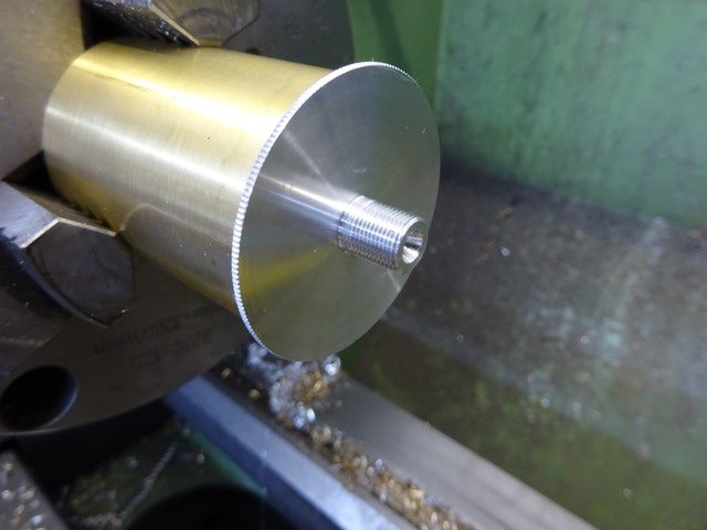
I was then able to use the float chamber as a means to hold the lid while the top was finished off.
An MDF plug was put into the chamber so it did not crush and then the bottom profile was completed.
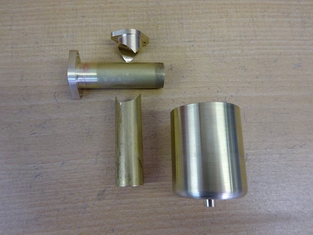
A disc of brass was bored and threaded 5/8 x 40tpi and then soldered onto a suitably threaded piece of 5/8" bar that had been drilled out to 1/2". This was then shaped into a flange on the rotary table.
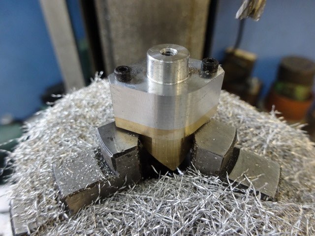
The top of the oil inlet and its flange are similarly shaped so first the ali top was turned
Then with it screwed to the brass both pieces were shaped at the same time with full depth cuts.
Another piece of hollowed out 5/8 bar was also needed to form the rest of the vertical inlet tube.
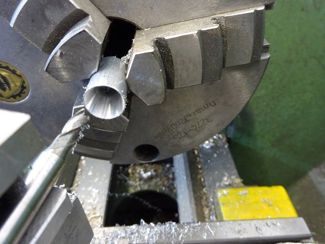
An aluminium venturi fits into the vertical tube, the taper was bored from each end using a 3-flute cutter held in the lathe tool post.
The throttle is a piece of 1/2" aluminium with a curved end, this not only slides across the top of the vertical tube to adjust the opening but the curve also smooths the airflow as it is turned from vertical to horizontal, the other two turned bits are a gland and lock nut to set the throttle.
See Part one here part two part three part four part five part six part seven part eight part nine part 10 part 11 part 12


