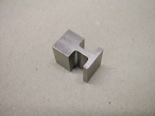
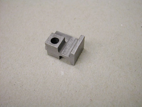
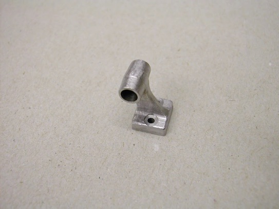
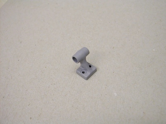
The throttle arm support bearing on the original design is just a small slab of 1/8 bar stood vertically with the bearing hole drilled through. It was felt that this would have been a small casting on the full size so this is what transpired...
After considering a composite - three parts, silver soldering, JB Weld etc it was decided to mill and turn it from solid.
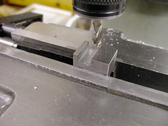
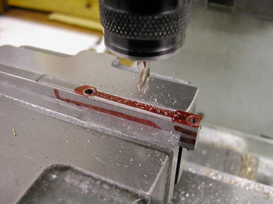
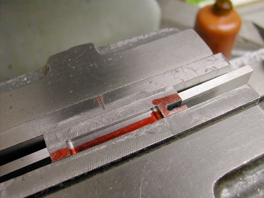
Began with a small block 15 x 12 x 10mm. After squaring up it was set at a 2 degree angle to mill the feet with a 'draft angle'. The 5mm FC3 cutter has had the corners 'radiused' by hand on the off-hand grinder.
The cross hole was drilled after carefully measuring the distance from the entablature to the centreline of the throttle rod but less carefully adding the two dimensions together and missing a whole mil off!
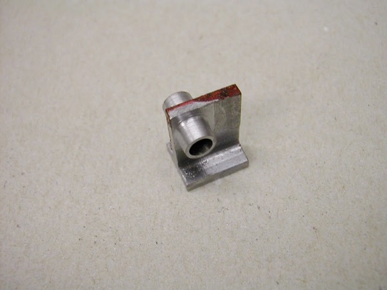
It was held on a small 4.0mm expanding mandrel and the housing each side turned, again at a 2 degree draft angle
then the surplus material was cut off on the bandsaw and the profile shaped by linishing and finally filing.
A 1.0mm shim was milled from the same material and bonded on with JB Weld then filed to flare in.
And a coat of primer brought it to life.
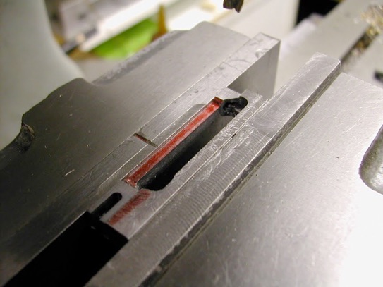
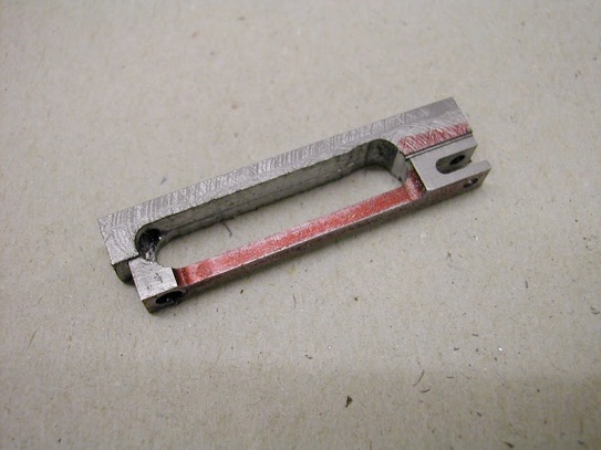
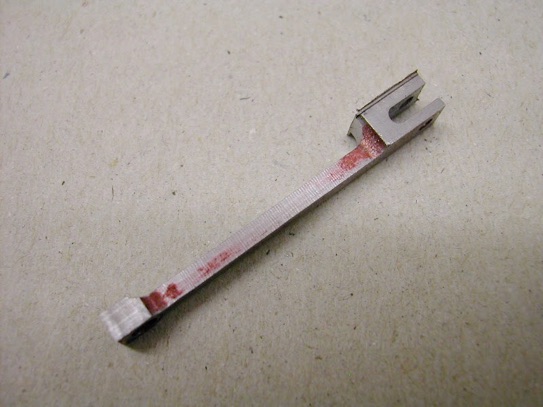
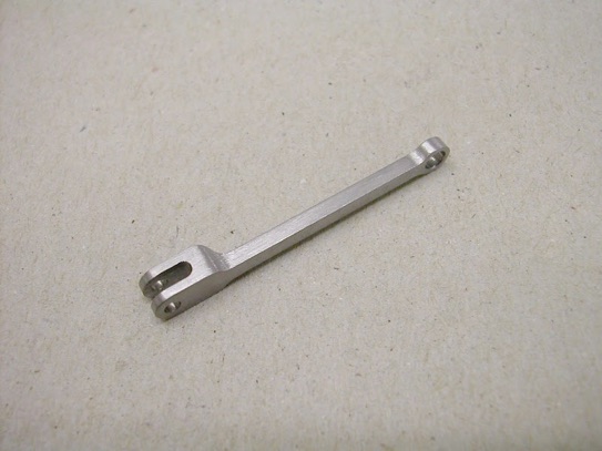
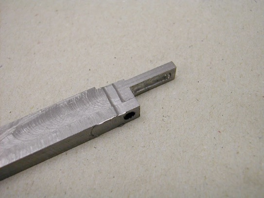
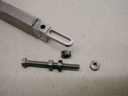
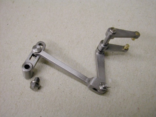
These last few parts for the governor linkage are not difficult things to make but can be a bit awkward to hold. Here's a few pics of the process. First off was the link rod and this was kept on the parent block as long as possible.
The sliding rocker arm was dealt with the same way.
The filing buttons were hardened as they were unable to roll. I have a few used needle files kept specially for this purpose as they do eventually suffer a bit on the hard surface
The boss was held on a small (3mm) mandrel for turning before filing the bottom end with more buttons
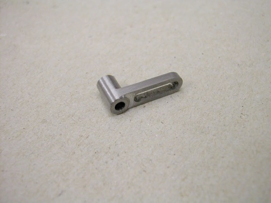
Ready to fit - the slot is about 12mm long
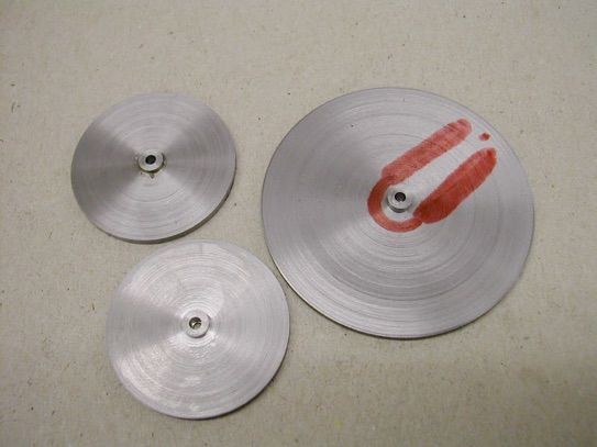
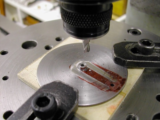
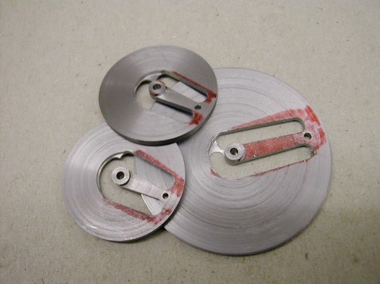
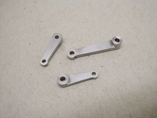
The rocker arms were even smaller and tapered. After some consideration I decide to make these from slices of round bar turning the bosses and finishing the bores on the lathe first then milling the profile using the rotary table to attain the angles. A bit wasteful of material but they were only thin slices and did provide excellent work-holding.
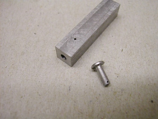
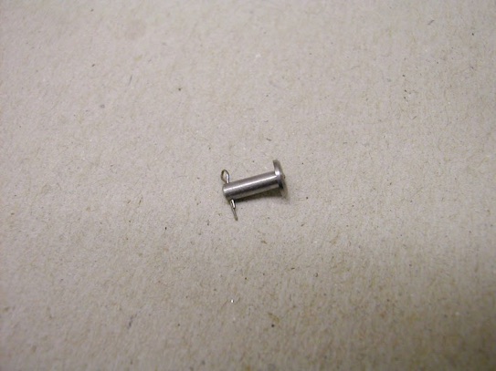
To prevent any likely nipping on the link arm I decided to use a split pin .
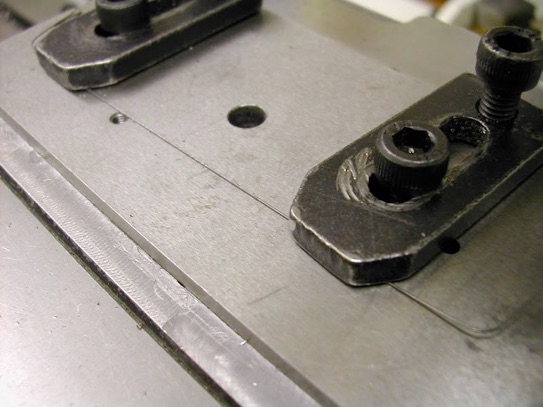
First off was to make a small jig to cross drill the .5mm hole (Pin is 2mm dia.)
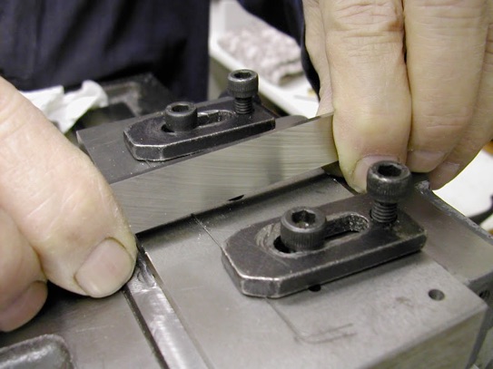
Next was to make the split pin. I used some 1/64 silver steel - yes, you are reading that right - and reduced the section to half round by clamping to a block of mild steel, pulling it as tight as possible, then scraping it with a piece of HSS before finishing it with a file. It was bent round a drill shank and nipped up with some small pliers - it's about 4mm long.
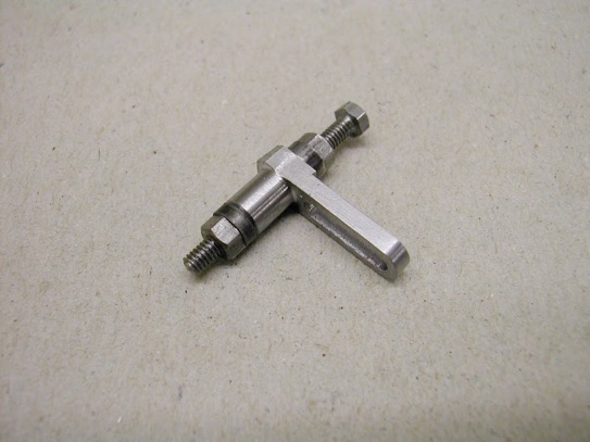
At last, with some guide pins turned from a piece of hardish bronze welding rod and Loctited into the arms, it could all be brought together.
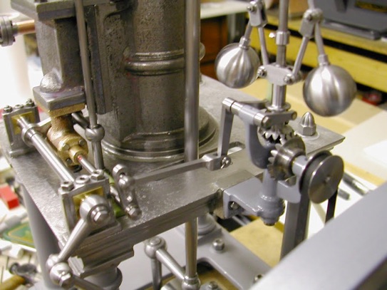
And finally, quickly assembled on the engine to see if it all worked freely enough.