WALLER TABLE ENGINE
By Ramon Wilson
8. Making the gears
6
3. Cder

Gear cutting was a new procedure for me. Many years ago, during training, a helical spur gear was cut on a universal mill along with a couple of straights but they were exercises and were of different DP so nothing meshed. This would be the first time on all fronts - home workshop, making tooling, making cutters, cutting the gears and getting them to work.

I took some pics along the way - I would stress though that they are not, most definitely not, intended to show anyone how to do it, but just to show those who, that like me before I began, may be considering the prospect of having to make some with a bit of cautious reserve.

I did not particularly want to delve into theory and calculations more than I needed to so kept my study as low key as I could. Just sufficient to get the job done was all that was really needed. I referred to the information set out in Ivan Law’s book regarding the layout of the bevels and also the information on making the tooling for making the cutters. However, I found a copy of an article from Model Engineer which gave a little more info on making the actual tooling and decided to use that.

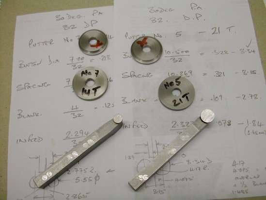
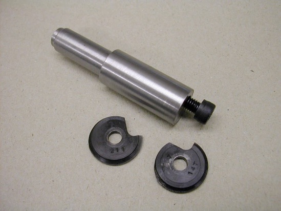
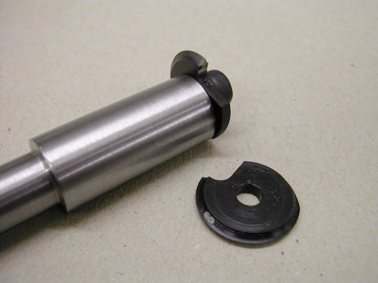
It was thought that instead of making the turning tool to cut both sides of the cutter at once that a single cutter would be easier to control and by turning the blank round would put the centre of the form exactly on centre line. Double cutters have to be exactly square to the blank and can create chatter. It seemed more practical to just use one and by turning the blank around ensure centrality. The chart showed two differing thicknesses for the blanks depending on the cutter number. If I were to do it again I would make all the blanks the thickest dimension so that once set up on the centre line this would not have to be changed. Obviously the thinner cutters would need reducing on their outer areas to the correct thickness as shown in the relevant charts. The blanks were made from slices of Silver Steel -from a bar of 1-1/4 diameter which I bought in my first year of model engineering - 1972. It had sat under the bench since then just waiting for a job!

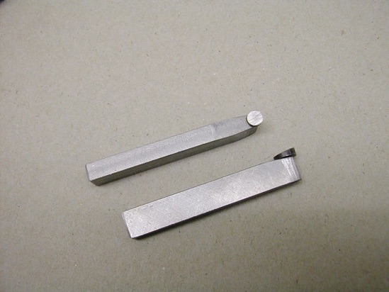
Two tool holders were milled from mild steel and the ends milled off at a 5 degree angle and drilled though square to that face to take the tooling buttons. The buttons were turned from silver steel and set up on the mill (that block again) and the tops milled off at a 10 degree angle. Heated to a bright red and quenched in oil they were left untempered for maximum hardness. The tops were then lapped with a diamond lap and finally stoned.
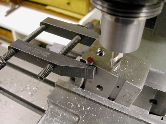
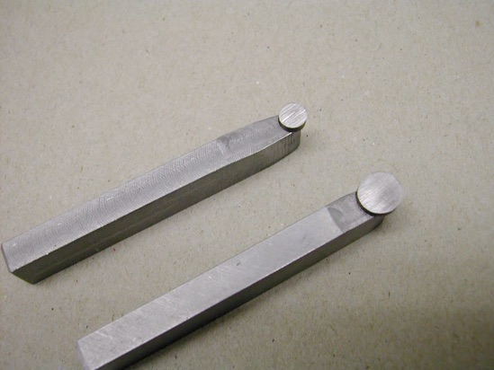
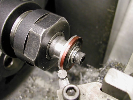
Notes were made for each cutter but this was where the first hiccup was made. The blanks were held on a mandrel and a facing cut was made to '0' the cross-slide. After setting the cutter off to one side the cutter was then fed in the required amount. Looking at the very small and obviously wrong form it took some while for the penny to drop that the in-feed was from the point of contact not from the previously set '0'.
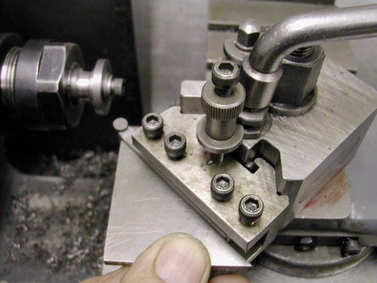
Also noticed at this time was the instruction in the book to rotate the buttons at 45 degrees facing inwards to present the fuller form to the blank. It was too late to do this as the buttons were Loctited in, so the tool holder was rotated at the required angle. Actually, this is probably best as this way it can be angled from both sides if required.
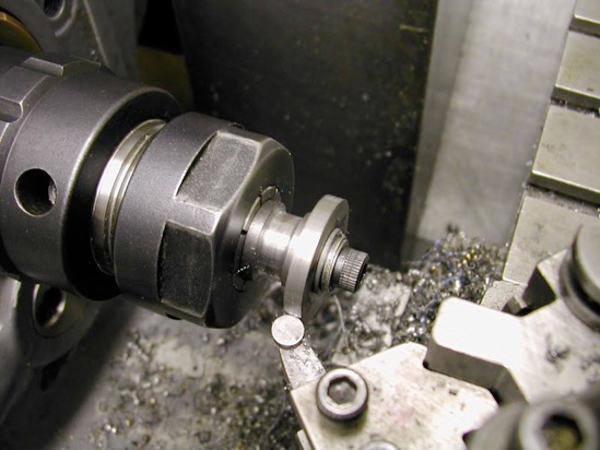
Once again a facing cut was made.
Then the blank was inked up and the cutter - set at the correct side offset - was brought in to just touch on then the dial was zeroed.
This time the form looked correct, the blank was removed and turned over then the tool taken in to the same setting.
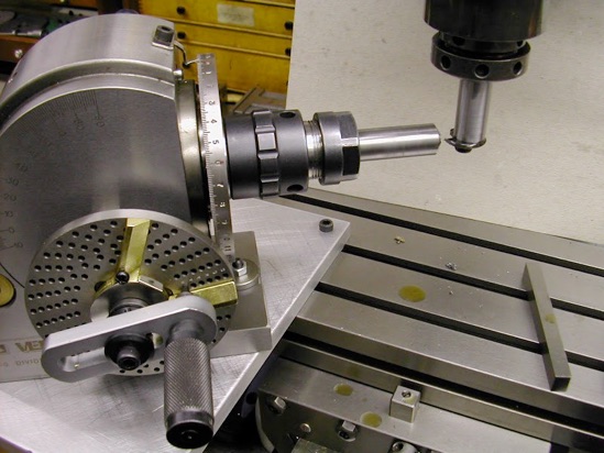
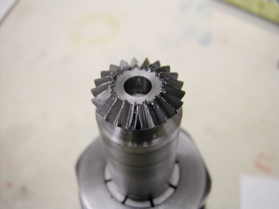
The dividing head  was set on a sub plate to get the travel past the cutter. The main gear was tackled first. The gears were cut using the parallel depth method, the cutter set to depth and the gap formed in one pass, winding the cutter back and forth a few times to 'clean' the surface.
Somehow, the calculator went awry and gave a wrong reading for setting on centre height. Confident it was correct I didn't check and milled what looked like a hypoid gear. Next attempt saw a loss of direction and a total mess up after five teeth and the third attempt went fine - until that last cut when it cut through the first tooth. It took some time before it was realised I'd made the classic mistake of counting the hole it started in as '1'.
Undeterred but beginning to get a bit anxious that one would ever materialise the fourth attempt went ok.
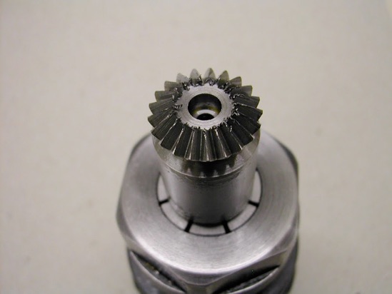
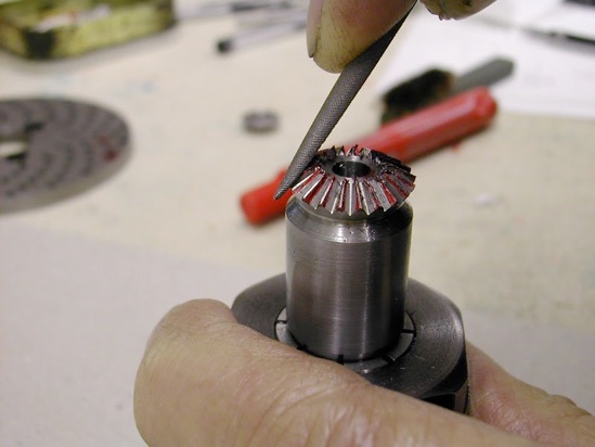
While it was still in the collet chuck it was deburred with a needle file and the outer tops of the teeth rounded slightly.
With new found confidence next up was the pinion. Leaving the head set at the same angle this was cut in the X-axis as opposed to the Y-axis for the main gear.
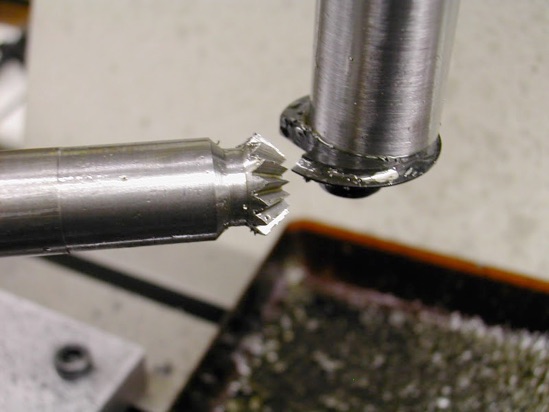
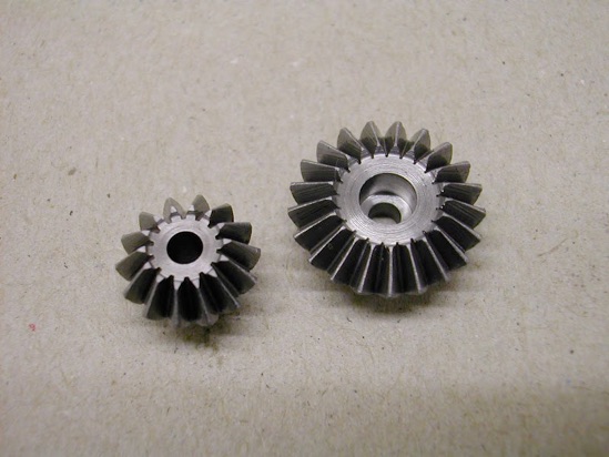
And the finished result - my first gears. Trial assembled on the governor and just running free they meshed and ran well without binding.
I'm not unaware that on the scale of things many have made far more esoteric gears at home than these, but these were my first and I was well pleased with the outcome. I have always baulked at the thought of doing them in the past having bought them when required but this bodes well for future projects. If you've never done it before I hope this will prove encouraging.


See Part One here  - Part 2   Part 3   Part 4   Part 5  Part 6   Part 7   Part 8  Part 9 Part 10   Part 11 Part 12   Part 13   Part 14