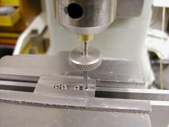
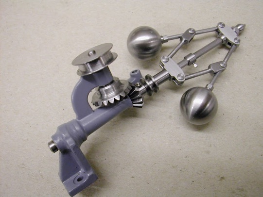
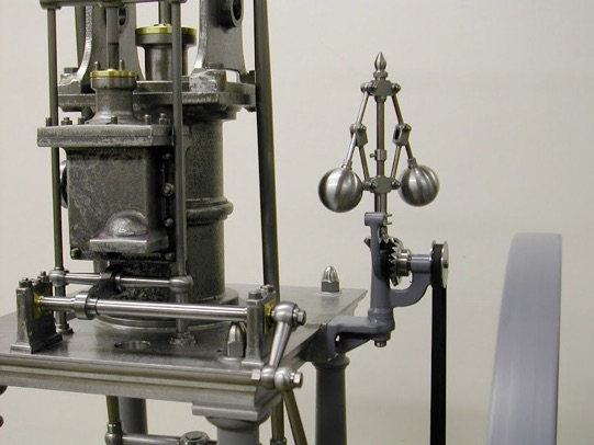
With the governor complete and fitted in place, small refinements included making a new bronze top bush for the standard with a slightly (0.15mm - 0.006" ) thicker top flange to lift the pinion a tad. The weight of the parts above were pushing the shaft down causing the pinion down onto the gear just a fraction too much. The second thing was to make a stop to restrict the outwards arm movement. To keep this reasonably in scale it required a small bolt and as such I turned the smallest item I think I've ever made...a square headed 14 BA bolt about 2.5mm long. I expect that may be big by some standards but it's certainly pretty tiny to me
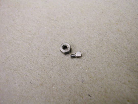
This is the bolt for the governor stop. The nut is a standard 10BA for comparison. The find of a 14BA die was somewhat opportune to say the least.
With regard to threading, many years ago when I bought my first sets of ME and BA taps and dies, and like most I made a tailstock die holder to use them in the lathe. Bought at an ME exhibition these were carbon and relatively cheap. It soon became apparent that some of the taps cut larger holes and some of the dies cut undersize - one was so bad that it literally reduced the size of the material rather than cut a thread. A call was made and the sage advice offered was to open them up by tightening the expanding screw. Well, it doesn't take long to realise that you can't exactly do that with a tailstock die holder - if the recess is big enough to allow the die to be expanded it must in turn put the die off centre! Hmmmm. However, if the die could 'float' then it may solve the problem. I have never seen this problem referred to nor indeed this 'solution' but some may find something in it's value.
Making separate flat die holders that could be 'backed up' by the existing tailstock die holder in order to keep them square, but which would have no influence on them other than pressure, solved the problem without having to source better quality dies.
In virtually all instances except that one bad die these have enabled threads to be cut with those original dies with controllable degrees of tolerance of tightness. The die holder, still there - just in case - has never actually been used in the manner it was intended since but purely as described.
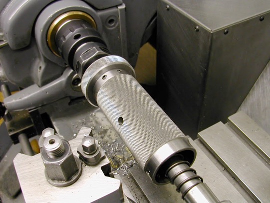
In use the tail stock die holder, which is spring loaded to present a degree of forward pressure to the floating die holder and maintain squareness as the thread progresses, is brought up to the the FDH and the FDH rotated by hand or held stationary as the chuck rotates if done under power. Most threads up to around 1/4 can be cut by (my) hand grip/torque alone and of course the smaller they are the more sensitivity you have on the cutting - in fact the holders are, if anything, rather heavy for the 14BA thread involved here to get any real feel but with care it did the job.
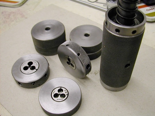
Seen below are the holders and blanks made some 30 years ago. There are in fact even more blanks as it was intended to have individual dies fitted ready to go - obviously that idea never got very far and the three you see are all that have been used over that time. They are easy enough to make, the only criteria being that the back face must be parallel with the face the die sits against. The die holder on the right is the original made at that time too.

With the exhaust flanges done it was time to make some nuts (8BA thread 9BA outer) and another perennial problem. In the past, nuts were always tackled by drilling a deepish hole into some hex bar, tapping as deep as possible then parting off. Parting off is always affected by the helix of the thread and there then follows an awkward second op to deburr the back of the nut.
It was time to improve matters on both counts ... and this worked really well.
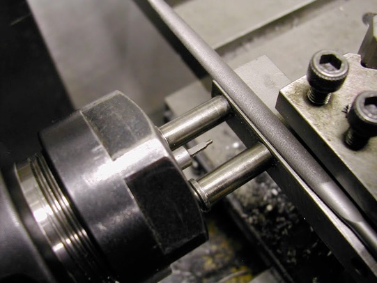
A brass bush about 25mm long was drilled to suit the tap shank - in this case #35 2.8mm (why is it taps never seem to have a consistent standard in shank sizes) and gripped firmly in the chuck. The tap shank was just a nice slide fit in this bush. The small piece of steel had a groove milled in to just take the hex blanks which had been pre-drilled, parted off and chamfered on each face. The tap wrench is just a slice of MS 16mm diameter about 5mm thick and gives more than sufficient torque for the task as well as giving far greater sensitivity. I found I could do four nuts at a time letting each one ride up the tap then sliding the next one along. In short a real big improvement from the previous method. Another bonus with this 'circular wrench' is that tapping is carried out using one hand. Also, in the smaller sizes theres probably no need for a flat on the tap the grub screw grip being more than adequate - any slippage possibly even providing a 'safety' factor. I can now see a series of such wrenches on the cards.