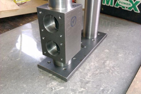
The next part, and probably the one with the most work in it, is the pair of columns and pump cylinder which were all one casting. I deliberated about how to best put this one together. My welding is not so good on internal corners, and there would be a lot of that involved, so I was not happy about being able to get a water tight joint and the welds would have been hard to get at to grind down to a nice neat fillet. The size of some of the bits of steel would have made it hard for me to get them up to a suitable temperature for silver solder to flow. So the only method left was sticking it together with JB Weld with a few dozen cap head screws thrown in for good measure.
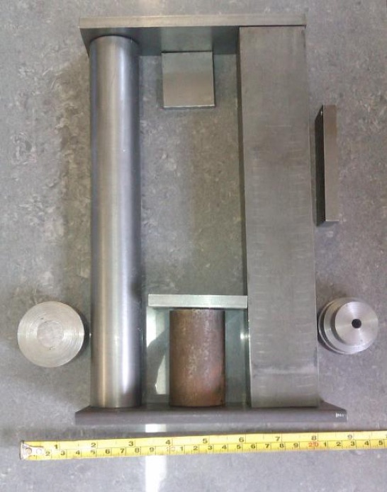
A few bits of metal were gathered together for the main parts.
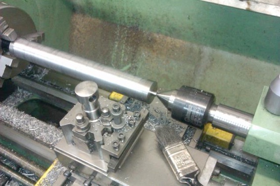
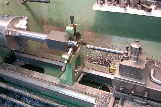
Starting with the round column this was faced to length and centred with the aid of the fixed steady then the 35mm bar (too big to fit inside the spindle) was reduced to 1.25" diameter along its length and a small 1/4" locating spigot turned on the top.
The lower half of the two columns are hollow and act as air chambers to even out the pump flow so the end had to be supported with the fixed steady while it was drilled 9/16" x 5" deep and a larger locating spigot added.
The 1.75" sq blank for the other column had to be milled to length and centred on the mill as the steady can not be used here.
In much the same way as the round column, this one was also turned down to 1.25" and the spigot formed. This is one job that I use the more pointed indexable tool for as it gives good clearance around the live centre, note that I am also using the back of the tool post which allows less tool overhang if the QCTP is not to hit the centre.
The other end was turned using tailstock support and then the fixed steady used on this round section while the hole was drilled then bored 17mm and part screw cut M18x1 for a depth of 4". The thread is to allow the valve seats to be screwed in from below.
I then completed the thread to its full form with taps which were just long enough!
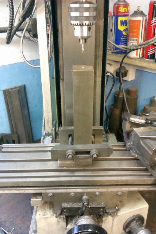
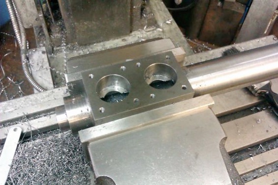
Moving over to the mill the two holes for the valve access covers were bored and the 8 stud holes drilled and tapped 5BA.
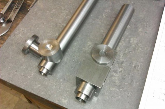
At the base of the round column there is a large round boss that has to be shaped to fit the column and also the outlet flange, these two cuts were done with the boring head.
And a quick mock up with some of the other flanges turned earlier
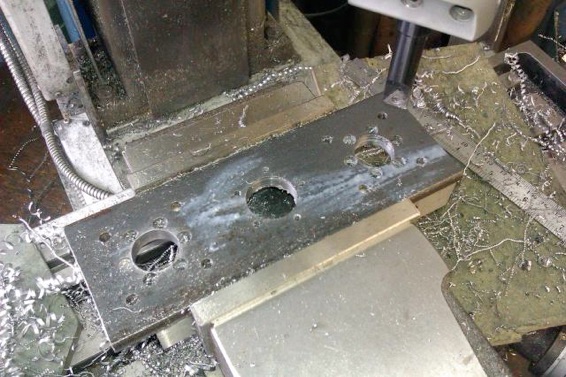
The base was cut from some 8mm x 60mm hot rolled, milled to length and then bored for the 3 locating spigots, 8 mounting studs and 19 counter bored holes for the M3 socket screws that will help hold things together on their correct PCDs. I find the commercial counterbores have too large a clearance hole for the thread so have a couple of old drills ground to 170ish degrees which seem to do the job.
And how the columns fit the base which will have further shaping done at a later date.

