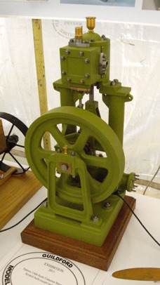
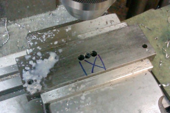
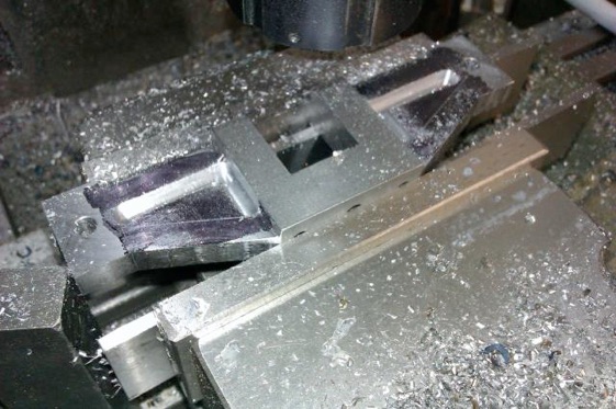
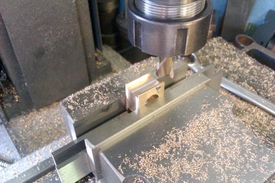
The other end of the crankshaft is supported by a bracket that spans between the two columns. A piece of 1/2" x 2" steel was cut then milled to length, the two mounting holes drilled and the bottom of the bearing pocket stitch drilled prior to hacksawing out.
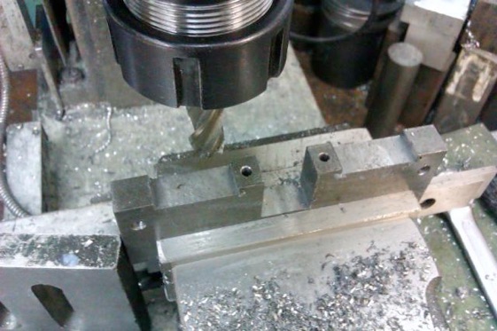
Once the waste was sawn out it was mounted upside-down in the vice and the bearing housing brought to size, the two holes for the bearing keeps drilled and a little milled away either side to get the required shape.
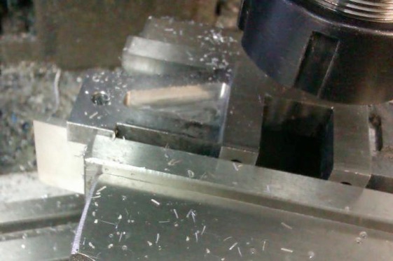
A flycuttter with a rounded edge to the HSS tool was used to thin down the ends on both sides which gave a nice radius fillet where the two different thicknesses meet.
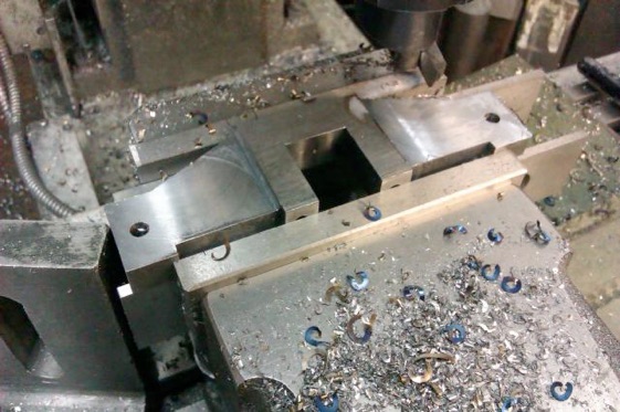
The top edge was then cut to slope down to the ends which were made a good firm fit in the brackets on the columns. I then started to mill out the triangular central section to thin it down to form a web, right angled cuts first.
I then rotated the vice and did the sloping edge and removed any waste between the outside cuts.
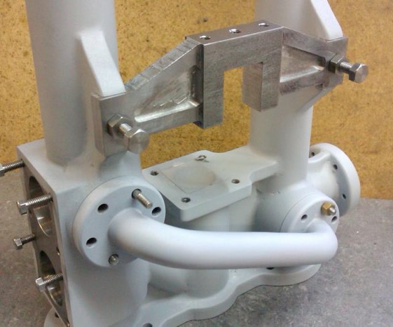
Here is a picture of the completed part being test fitted, just needs the arrises knocking off and the internal corners filleted with Milliput.
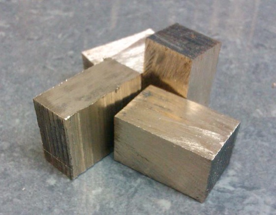
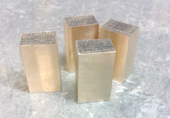
Four bits of bronze were sawn off to form the bearings.
These were then machined over size with a flycutter.
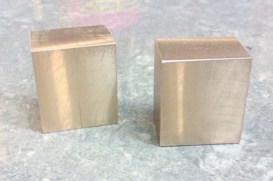
After soft soldering together the were brought to finished size, again with a flycutter.
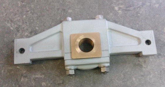
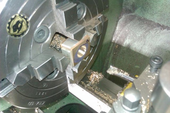
The centre of the hole was marked out and set to run true in the 4-jaw chuck before drilling and finally boring to a nice fit on the 1/2" crankshaft material.
Taking a sharp 2 flute milling cutter the location slots were milled on the two opposite sides to fit the 1/2" bearing housings.
Finally an oil hole was added, the corners rounded with a file and a quick rub on some fine emery to clean them up. I'll not split them until final assembly as it makes it easier to leave them as one while test fitting the engine.
Next time: machining cylinders from cast iron bar.
GO TO PART ONE PART TWO PART THREE PART FOUR PART FIVE SIX SEVEN EIGHT NINE TEN ELEVEN TWELVE THIRTEEN FOURTEEN FIFTEEN

