DELAGE GRAND PRIX ENGINE PROJECT
Part eight by Mike Sayers

DELAGE GRAND PRIX ENGINE PROJECT
Part eight by Mike Sayers

Next up was the manifold. Below is the full-size engine in all its glory.
The manifold is a beautiful piece of work with the pipe bending a refined piece of craftsmanship.
The actual manifold is made out of steel, and is prefabricated and nickel plated.
There are no parallel sides or straight forward pieces on it.

It was not possible replicate the form of the small pipe with its sharp bend.

Here, a 12mm copper tube is being formed with the tool. First tried bending it with a mandrel inside to keep the section right throughout the radius. The mandrel didn’t work.
Then made an ordinary ‘pull bender’. As can be seen in the photo, the problem is that when bending a piece of pipe, the pipe has to be secured very firmly while the operation is on a very small area of pipe in the radius.
Two metres of pipe were consumed trying to make the nine bends and the tapered tubes required for the manifold, so it was quite a wasteful operation.
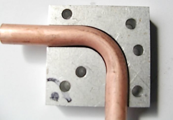
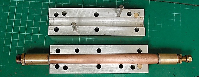
As can be seen in the first photograph of the model, all the small pipes are in full view on the side of the engine. Wanting to improve the section, the light alloy mould blocks were made as seen below. Reshaping the pipe to a circular section in the mould, initially by using pressurized water at 400psi and was pressurized using the Pickering Society boiler testing pump. However, more pressure was required to get it right.
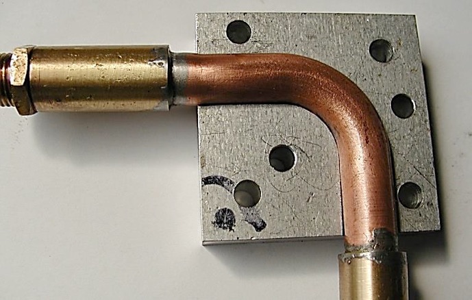
The ‘Heath Robinson’ arrangement seen below, utilized the pump from an old hydraulic press and used oil on a total loss system. This meant the pump body had to be kept replenished with oil. That system worked, and the section was really improved all the way around.


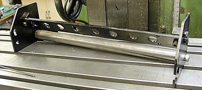
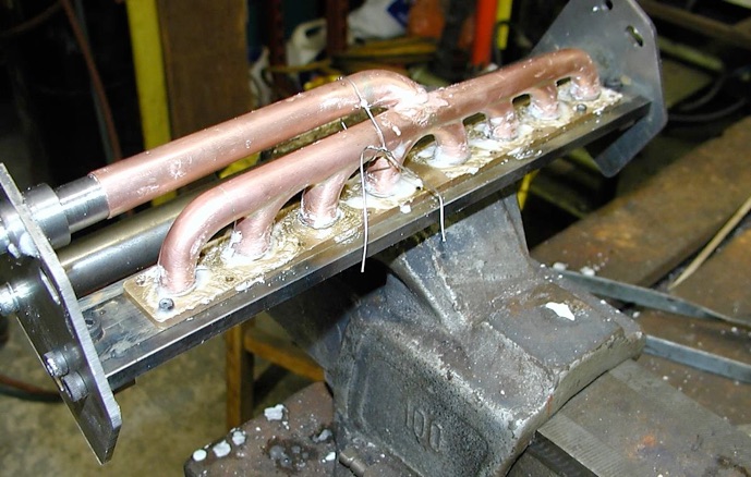
Also needed was a jig to hold all the manifold components in alignment while silver soldering the whole assembly.
The jig was designed to hold the components in the three stages of silver soldering:
•The first stage was to solder up the piece serving the front four ports. A tapered rod was screwed to the opposite end plate on the jig to engage in the tapered tube to hold it in line while it was being soldered.
•The second operation was to solder up the part serving the rear four cylinders. The front section was removed from the jig and the tapered guide was then fitted to the opposite end plate in order to support the rear section in the same way as the forward section. The method ensured that the front and rear parts would line up correctly at the centre.
•A further tapered guide was screwed into the front (right hand as seen on the photo) jig plate to support the third tapered section which is the lower tube connecting to the super charger joint. This ensured that that part was kept in the correct alignment during soldering.
Unlike an exhaust, one end of the manifold is not just ‘waving in the breeze’, every part has to line up and fit exactly at a number of locations. There is no margin for error. At the supercharger joint there is also a fine thread union.
First the jig plate had to be machined off the back of the manifold, and then the whole of the back of the manifold mounting flange had to be ‘fly cut’, as it was damaged.
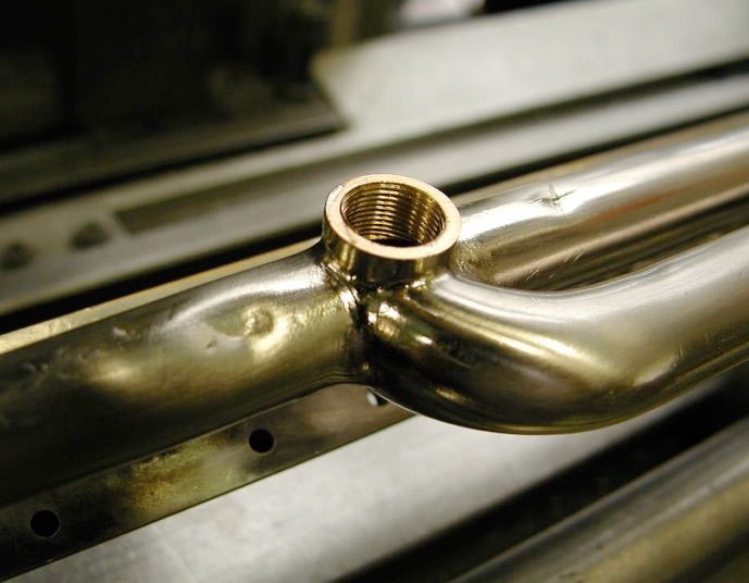
Please Note: The two photos below are for illustrative purposes only, as the manifold had not been nickel plated at this stage of operations.


This meant the screw thread had to be tapped out, which was the last intended operation on the manifold. Unfortunately, before that could happen a spanner was dropped.
Part one here. Part two here. Part three here. Part four here. Part five Part six Part seven Part eight