
BUILDING AN ECONOMY
HIT & MISS ENGINE
Part five - conclusion
by John Merrett

-
44.Plinth base
As the aluminium engine base was referred to as a “base” I have decided to call this the plinth to avoid confusion. This structure is required to enlarge the base area and, more importantly, to house the ignition system.
The ignition on this engine uses a trembler coil to produce the very high voltage fed to the spark plug. As a complete unit was available from L.A. Services, one was put on order and arrived a couple of days later.
Elderly readers of my vintage will understand when I say this American product reminded me of a piece of school physics laboratory equipment! The transformer coils were housed in a dove tailed wooden box with the trembler points on the end and terminals on the side.
It all works as follows: You feed the Low Tension points on the engine with the battery voltage and as the points close just before top dead centre, the trembler points and coils are activated. The resulting pulse of High Tension Voltage (many thousands) going to the spark plug. The kick you get if you accidentally brush the plug with your hand when energised is pretty frightening & certainly not recommended!
The plinth is constructed of wood as can be seen in picture 45, the studs to hold down the engine are bonded in, the low and high tension wiring is passed through guides made from tube as can be seen in picture 44.
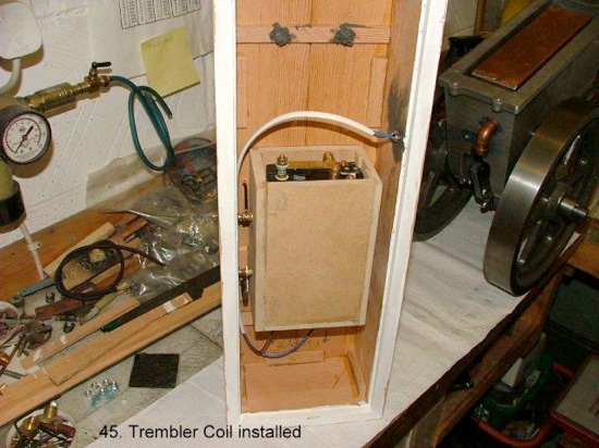
A secondary box/drawer was made of M.D.F to house the trembler coil. The white wire you can see is the 12V battery feed from a coaxial plug and socket through the back side of the plinth. The whole construction was undercoated and painted a neutral colour in an attempt to simulate a stone foundation. At each end, inside wood reinforcement was added to strengthen the top of the plinth & steel plates on top, outside, to allow 8mm studs to pass through to a set of bearers (see pic. 47).

46. Engine on plinth
Here you see the first fitting of the completed engine prior to painting, fixed on the studs and the low and high tension wires coming up from the trembler coil, through the tubes and made off at the contact breaker and the spark plug respectively.

47. Bearers beneath the plinth
Before attempting to start the engine I realised that with an unbalanced crank and heavy connecting rod the engine would need to be fixed down to stop it “walking” all over the garage floor! The metric equivalent of 3” by 2” wood was made up into a set of bearers as in Pic. 47. My suspicions were borne out when attempting to run later and, in fact, the bearers had to be drilled each end for coach bolts to screw into two blocks of 6” by 6” oak (ex gate post).
This arrangement eventually kept the running engine in one place! The picture also shows another fitting not mentioned earlier. The cylinder liner is of course surrounded by water which is held in the hopper. To drain it, the cylinder casting is provided with a boss underneath, behind the cylinder head, to drill and tap for a drain plug. This is not the easiest place to access, so I made and fitted a drain valve with a discharge pipe to allow the water/antifreeze to be run into a jar between the bearers. The copper drain pipe can be seen emerging from under the cylinder head.
Time now to try out the starting handle and get it to fire. I was told to aim for between 5° & 10° spark advance so I made up a cardboard 7.5° gauge to place on the crank web whilst sliding the L.T contact along until the trembler starts to buzz and locking it.
Petrol was put in the tank, bearings oiled up, battery switched on, choke closed, fuel needle valve opened, exhaust valve held open and the flywheels cranked up with the handle.
The valve was let go and ‘bang!’ It fired. The choke was reduced, it ran for a few revolutions, then stopped.
To cut a long story short, I got very frustrated, the plug would either wet out on starting or carbon up and short out after about a 5min. run. It seemed that reducing the fuel was not possible as the engine slowed and stopped.
Eventually after much fiddling with different settings longer runs were possible and higher speeds were achieved to enable the governor to trigger the valve push rod to hold open the exhaust valve dropping the speed back to release the push rod again.
Putting hot water in the hopper got over the initial plug wetting but I rarely got a run of more than 30 min. before the plug needed a clean, using an adapter on to a small grit blaster to clean fully down the centre electrode ceramic insulator; don‘t forget to blow out the abrasive dust before re-fitting the plug!
I put everything to one side for the summer season and kept thinking about the problem. One day I recalled having read a series in the Model Engineer about a freelance hit & miss engine named Rina, made up from bits of material from the scrap box. The significant part was the fact that it was running on gas not petrol.
I searched back and found the articles which contained a drawing of the gas carburettor based on a very old design by the famous model I.C. engine designer, Edgar T. Westbury.
Nothing tried, nothing ventured, as they say and le’ts face it the engine is a gas engine! I believe the supplier does have a design for a gas carburettor basically like the petrol one and a zero pressure regulator, but I wanted to use a low pressure barbeque regulator so decided to have a go at this design.
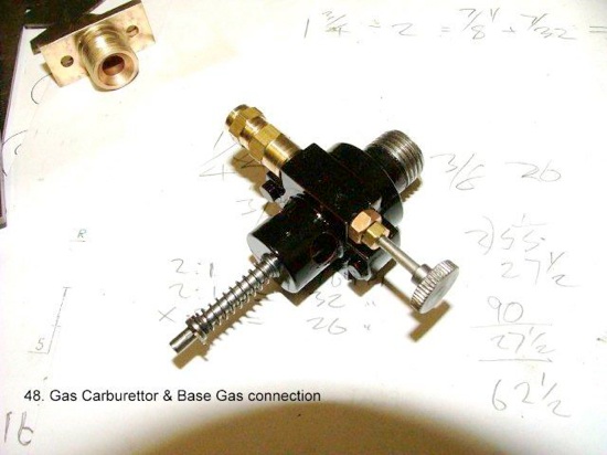
48. Gas carburettor
My engine was about double the volume of this smaller unit so I grabbed a piece of paper and drew up something similar nearly twice the size. The end result is shown in the centre of picture 48. It works as follows:
The gas comes in at the top left union, controlled by the needle valve bottom right. The light spring and spindle are part of a poppet valve seated in the main body. The clever part is the fact that the gas from the needle valve is ported to a small hole drilled in the poppet valve seating, sealing the gas supply until the engine inlet valve opens, sucking open the poppet valve which meters a fixed amount of gas into the air being drawn in. what is not clear in my picture, is how the air actually gets in. The cylindrical part where the spindle enters is hollow and is radially drilled with four large holes for air to enter beneath the poppet valve. Believe me the holes are there but not visible in the picture because of the black painted body.
The brass union with a rectangular flange in the top left corner is the connection I fitted in the back of the plinth to connect a Sievert hose union and pipe the gas up through the plinth to the carburettor.
I did not have a tap or die for this connection so had to screw cut it on the lathe.
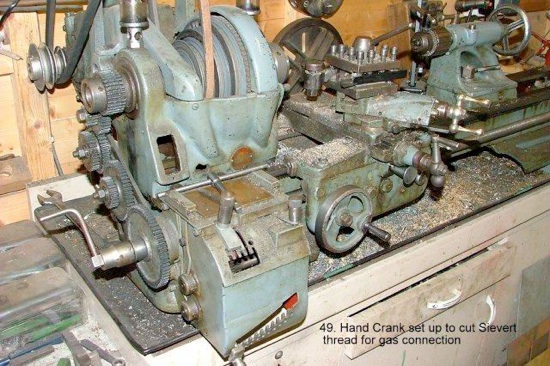
49. Screwcutting the Sievert thread
I never trust myself screw cutting a short thread up to a shoulder and disengaging the half nut under power. The picture 49 shows my trusty old Atlas lathe & the set up for this tricky operation.
I managed to approximate the pitch of the thread using a combination of gear train & gearbox, I then put a crank handle on the input shaft to the gearbox, thus driving the leadscrew and lathe spindle together. The other advantage is there is no need to disengage the half nut, just withdraw the cross slide and wind back.
Having achieved a good thread using a spare Sievert union nut as a gauge I finished machining both ends and the bore before silver soldering on the rectangular flange.
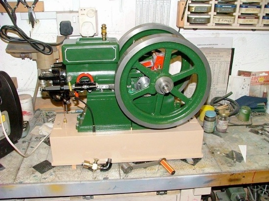
50. Finished and painted
The engine performed like a dream when running on butane gas, starting easily from cold on a fixed needle valve setting and continued to run for an hour or more until I felt the oilers needed replenishing.
One thing I did find was that the compression spring on the poppet valve spindle (see pic. 48) was a critical component. My first spring worked but the engine speed would not increase over the whole range. I made another slightly stronger spring which completely solved the problem.
I tried it on propane. It is well known that the extra carbon content gives a hotter flame for brazing; the engine ran exactly as butane but became quite hot after a relatively short run. I could see no advantage in using this gas in fact I wonder whether the extra heat might burn out the stainless valve heads.
I have paint spraying equipment, including a touch up gun and air brushes. However, I hand painted the crank webs and con-rod flutes using Craftmaster red and used aerosol sprays for etching primer, undercoats and final green gloss from the local motor accessory shop.
I do all my lining with a draughtsman’s pen and I make chamfered Perspex stencils to create the corner flutes.

51. Running on gas
My last picture shows the set up for running on gas with the Calor Gas cylinder in the background. You will see I have added a driving pulley onto the end of the crankshaft with the idea that I may build a saw bench with a flat belt drive.
I made a simple pattern out of laminated & glued M.D.F for the extra pulley & had it cast in fine grain iron at our local Norfolk foundry.
You will also note the heavy blocks of oak attached to the bearers referred to earlier, although I have found that they are not so necessary with gas operation.
In my view a petrol explosion in the cylinder was more violent than the burning of gas so the shock of the reaction on the piston with petrol was adding to the out of balance crank. I believe the combustion of gas is a slower process creating a softer performance!
To conclude; I thoroughly enjoyed the engineering challenges and precision associated with this engine compared to steam engines and would definitely recommend others to try their hand at this gas engine or something similar if they have not done so before.
MEWS IS SPONSORED BY - HARROGATE EXHIBITION - TEE PUBLISHING - MERIDIENNE EXHIBITIONS - LYNX MODELS - CAMDEN MINIATURE STEAM - TRANSWAVE CONVERTERS - MESSE SINSHEIM - CHRONOS - PAULTHECAD.CO.UK - ECCENTRIC ENGINEERING