BUILDING AN ECONOMY
HIT & MISS ENGINE
Part four
by John Merrett

BUILDING AN ECONOMY
HIT & MISS ENGINE
Part four
by John Merrett
Many stationary engines of this type had the same style of simple silencer consisting of two dished halves creating an expansion chamber, one with the inlet connection and bolted together to form a narrow annular exhaust passage. I expected the two halves to be supplied as basic castings but looking at the drawing it became obvious that these halves were to be machined from solid bar!

The amount of material left after the two halves were finished was probably about 5% so you can imagine the quantity of swarf produced. However many scouring pads it would have made I have no idea but I can reveal that I nearly lost sight of the lathe in it all, and had to dig it out at least three times.
The final operation was to machine up the little spacer washers, drill the bolt holes through the to halves and then bolt together.


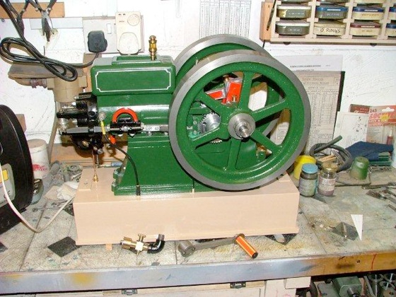
Note the silencer screwed to the exhaust outlet on the cylinder using a commercial 1/4” BSP. male to female pipe elbow.


Because the valves are exposed on this engine, the technique for starting is to hold the rocker down with a finger, spin up the flywheels and release the valve. With carburettor set up correctly the engine should fire up.
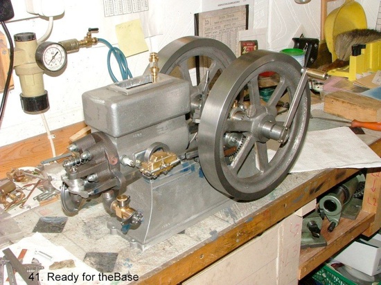
We are, however, getting ahead of ourselves as we haven’t got a petrol tank yet.

Having a sheet of copper handy of about 20 SWG. this was used to construct the tank by folding up four sides and two ends with appropriate tabs for soldering. The unsoldered tank was tried in position and the inlet and pipe feed hole centres marked in situ. The feed pipe was formed and vee’d at the suction end to ensure a clear passage on the tank bottom at the suction end and silver soldered into the tank end.
At the other end a brass bush was silver soldered in to take the filler which had to be screwed in when the tank was fitted into the base. The tank was pickled in citric acid to thoroughly clean the copper and could then be soft soldered with Tinman’s solder and Baker’s fluid flux, without any fear of melting the connections.
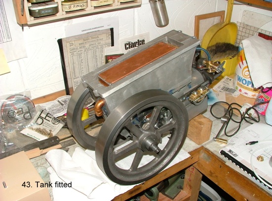
The petrol tank was eased into the wooden guides and the filler screwed into the bush in the end of the tank. The tank was then fixed to the wooden guides by applying silicone sealant which bonded to the tank and the wood.
MEWS IS SPONSORED BY - BRISTOL EXHIBITION - HARROGATE EXHIBITION - TEE PUBLISHING - MERIDIENNE EXHIBITIONS - LYNX MODELS - CAMDEN MINIATURE STEAM - TRANSWAVE CONVERTERS - MESSE SINSHEIM - CHRONOS - PAULTHECAD.CO.UK - ECCENTRIC ENGINEERING - WARCO -