BUILDING AN ECONOMY
HIT & MISS ENGINE
Part three
by John Merrett

BUILDING AN ECONOMY
HIT & MISS ENGINE
Part three
by John Merrett

The five stud holes were marked out, spot faced, centred and drilled for the metric studding. The head was then clamped onto the cylinder and the stud holes spotted through followed by drilling and tapping the cylinder for the studs.
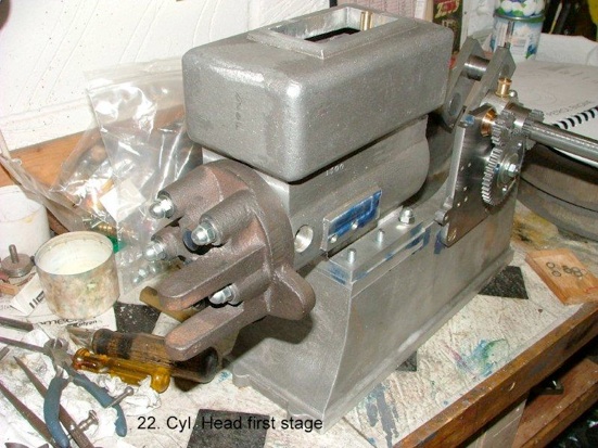
An aluminium block was turned up to the cylinder diameter and two grooves milled down the side to clear the cast valve rocker supports (see later picture 26). Stud holes were drilled and tapped and a set of short studs screwed in. The cylinder head gasket face and raised valve face were then machined using a live centre to hold the head against the aluminium jig.
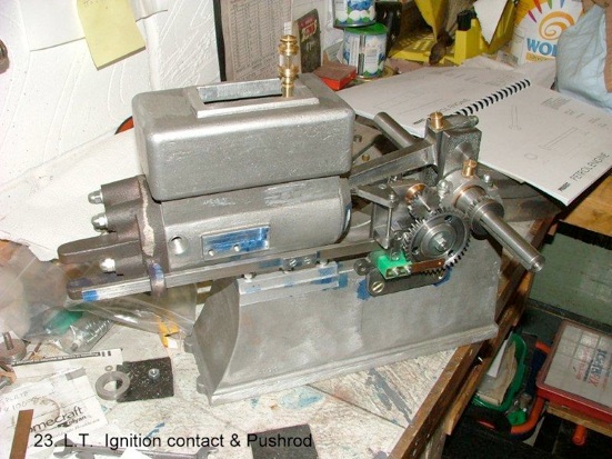
The low tension contact breaker consists of a PTFE block (green) with a beryllium copper slotted spring leaf and a copper rivet at the far end. When the engine is near completion, the gauge plate exhaust cam behind the 2:1 gear, can be set and a rivet positioned in the large gear to give the approximate timing which can be accurately set by sliding the leaf along the PTFE block. (Hope that description is clear!)
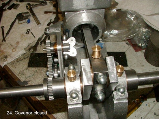
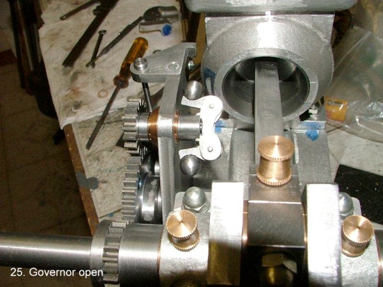
Before further work on the cylinder the ball governor was a nice little diversion from heavier engineering! The ball links operate a push rod through the centre of the governor gear shaft. This rod in turn, operates a crank lever against a light spring with an extension bar to interrupt a catch plate screwed to the valve push rod, holding the valve open until the revs. fall back!
The steel balls were turned to size using a spherical turning attachment I made many years ago when making the governor for my 3” Burrell traction engine.
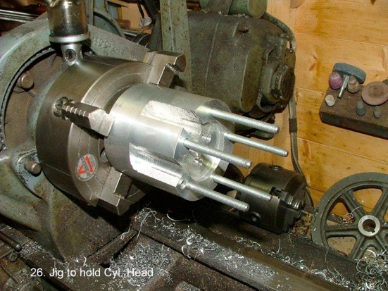
This is the aluminium jig with milled slots and full length studs, referred to earlier, for all the further operations on the cylinder head. It is mounted in a four jaw independent chuck so that different centres can be achieved.
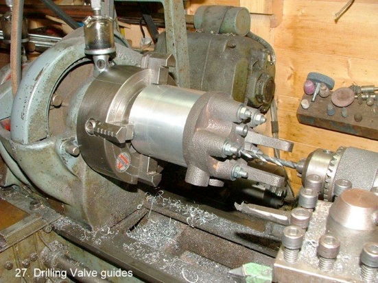
The valve guides were drilled and reamed ¼” with the head mounted as shown.

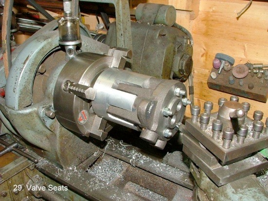
This picture shows the cylinder reversed on the studs ready for the guide holes to be opened out to ½” for inlet and exhaust gas clearance and then coning of the valve seats. Note the rocker supports nestling in the milled slots.
The valve stem bores had to be very carefully centred using a Verdict internal dial indicator to ensure the seats were absolutely concentric.
Having centred the first valve guide the holes were enlarged to ½” to the appropriate depth and the top slide set at 45 deg. So the valve seat could be created. The whole assembly was then moved across and the second one completed.
The top slide setting must not be touched until the valve heads themselves are machined.
To complete the cylinder head, the inlet and exhaust connections and porting were drilled, tapped and plugged where necessary as were the rocker shaft bearings.
Unfortunately I omitted to take any pictures of the valves during construction. Although specified as turned from solid stainless steel bar I decided to make the stems from ¼” ground silver steel, reducing down and threading the ends for ½”. Two short pieces of 5/8” dia. stainless bar were drilled and tapped to take the stems, which were screwed in tightly with permanent Loctite. The stems were held in a ¼” collet and the stainless heads roughed out to shape. The stems behind the heads were then cross drilled and small taper pins hammered in to ensure nothing came loose in operation! They were each put back in the collet for final machining including the valve seating surface.
Finally, the heads were marked “I” and “E” and lapped into the seats in the head using two grades of valve lapping compound.
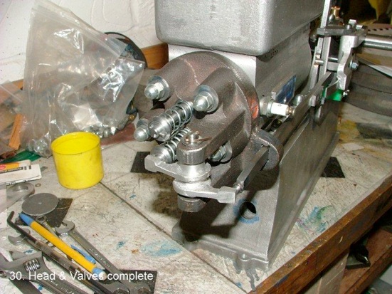
The spring locators were machined from mild steel, the valve spindles cross drilled for the retaining pins and the springs fitted and pinned. The inlet spring is quite light as it is only opened by the suction from the piston when it performs the inlet stroke of the four stroke cycle.
The cast aluminium exhaust rocker was then machined/filed and fitted with the rocker shaft as seen above.
A gasket was cut and punched, smeared with a little silicone gasket sealant and the head pulled home evenly with the metric cap nuts and washers.
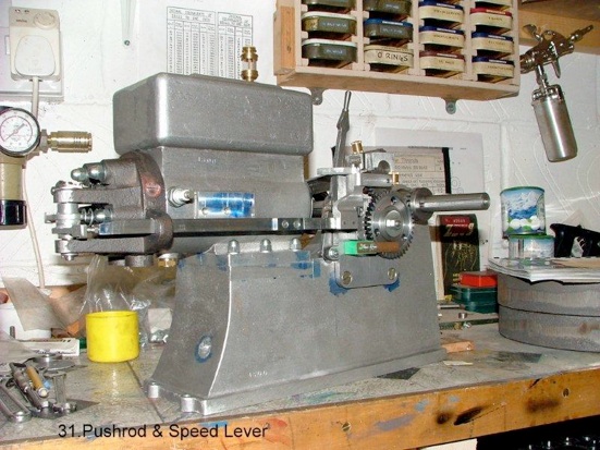
The latching mechanism to limit the speed of the engine has a speed lever, seen behind the water hopper, which moves the feedback spring along the trip lever, changing the opposing force against the force from the governor.
This lever and the trip mechanism can also be seen in the following picture No.32.

Once again you can see the speed lever and the crank/lever with its arm just clear of the trip plate on the pushrod.
The strange looking brass object is the dummy magneto, just there for appearances. Quite a tricky bit of fabrication and a lot of hours spent on a piece of decoration.
On the full size engine this is a permanent magnet and semi rotary coil device which would be triggered by the valve push rod which runs behind it. On this model the H.T. current to the plug is produced by a trembler coil hidden in the base which in turn is triggered by the L.T. contact breaker, producing thousands of volts to the plug and guaranteed to de-fibrillate any unwary recipient!
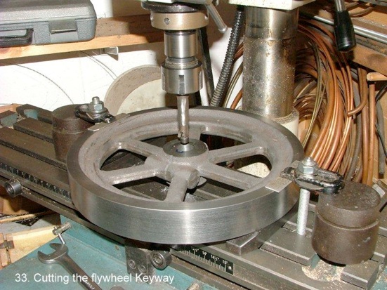
It would be nice if I had a set of broaches and a press to use them to cut keyways with; but I haven’t! I know its not the right way to treat a vertical mill but, when needs must, it has to be pressed into service as a form of vertical shaper. The spindle was locked from rotating and the quill racked up and down, slowly advancing the mill table a few thou at a time, using a specially ground tool in one of my small fly cutter holders. It takes a lot of time but the resultant keyway is quite passable. The keys were cut and filed from gauge plate with the normal piece on the end so it can be removed by hammering a taper wedge in between the wheel boss and the key end.
MEWS IS SPONSORED BY - BRISTOL EXHIBITION - HARROGATE EXHIBITION - TEE PUBLISHING - MERIDIENNE EXHIBITIONS - LYNX MODELS - CAMDEN MINIATURE STEAM - TRANSWAVE CONVERTERS - MESSE SINSHEIM - CHRONOS - PAULTHECAD.CO.UK - GLR DISTRIBUTORS - ECCENTRIC ENGINEERING - WARCO -