BUILDING AN ECONOMY
HIT & MISS ENGINE
Part two
by John Merrett

BUILDING AN ECONOMY
HIT & MISS ENGINE
Part two
by John Merrett
Continued from part one.
The bearing cap mating faces needed machining and drilling for the four studs, cap nuts and washers. The caps were securely bolted to the base which was then clamped on its side to the mill table with an assortment of packing pieces to allow the caps and body to be bored for the bearings parallel to the bottom of the base and at right angles to the centre line of the cylinder. The special boring bar was setup to produce the exact bore and passed through both sides one after the other.
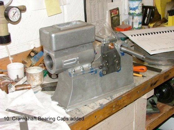
Spot facing was then carried out on both sides of the bearing seats to the exact width for the bushes.
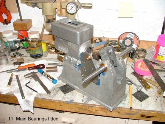
Normally, you would expect the bearings to be split but they are not on this engine. Perhaps this is due to the fact that the gunmetal bearings are of considerable proportions and I have to admit that after many hours running there is no detectable wear.
The bearings are a tight fit in the bores and a good fit on the crankshaft journals. They have small flanges on each end (hence the need to spot face the bores) to prevent any side movement. A lubrication hole was drilled in each bearing cap and used to spot through to the bearings which were then drilled with oil passages. To ensure the bearing oil hole stays in line with the hole in the cap a small tube with a coned end was inserted down the cap hole to engage the bearing hole and prevent any possibility of the bearing rotating in the housing. This tube was held down by the later addition of the oiler cup screwed into bearing cap. A clever and effective arrangement.
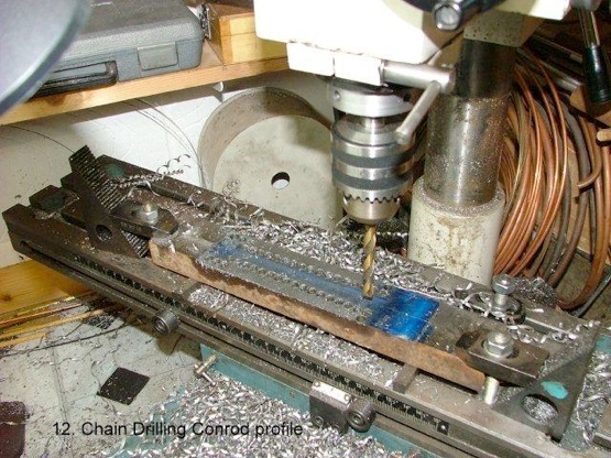
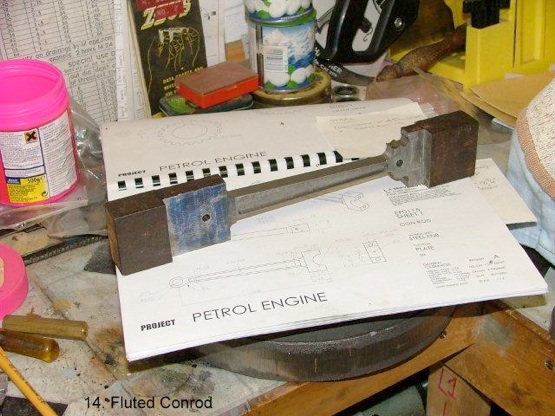
As you can see the con rod started life as a pretty hefty chunk of scrap steel, something like 2” by 1” and long enough to allow plenty of extra to clamp down on the mill. Even the big end finished size was only 42 mm. by 16 mm. which meant a great deal of metal needed to be removed.
After facing the top and marking out with blue and scribing the tapered shape it was chain drilled with the holes just touching, as in Pic. 12 so that the excess could be removed by chiseling into the thin metal between the holes.

The con rod was turned over and faced down to the correct thickness of the big end using my triple tip facing cutter with a No.3 Morse taper pulled in by a drawbar, as illustrated.
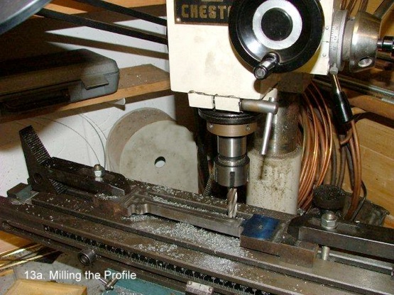
Having reduced the rod to thickness, the remains of the chain drilling were removed by using the side of an end mill which also produced the correct radius at big and little ends.
After each side was profiled, the fluting was carried out using the same end mill and pilot reference holes drilled for boring the bearings. Having removed the rod from the mill, the waste material was cut off and the big end drilled tapping size for the studs that would hold the split big end and split bearings together. The big end was cut in half, faces machined, clearance holes made in the loose half and the other half tapped M6. Studs were made and fitted and the bearing cap attached tightly with M6 cap nuts and washer
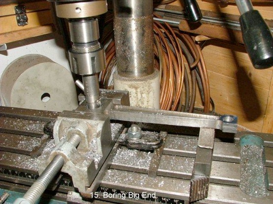
The big end was bored as in Pic. 15 above using the mill and a simple adjustable boring bar, the little end was drilled out by centring on the pilot hole. The little end was left unshaped so it could be tightly clamped when drilling the bearing hole.

The rod, prior to shaping the little end.
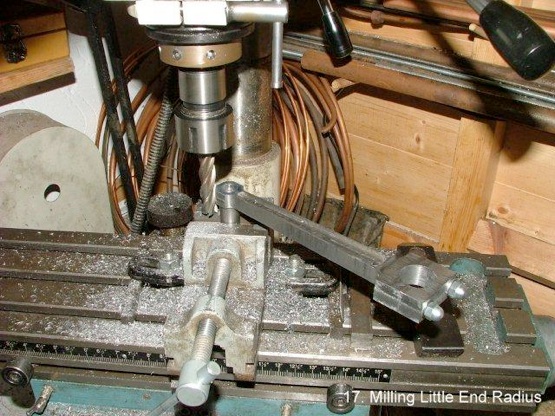
A machined spigot was clamped in the vice on the milling table and the little end carefully rotated by hand, taking light cuts ‘till the correct radius cutter just blends into the straight section of the main rod.
Unfortunately, there are no pictures of the gunmetal big and little end bearings being machined.
The little end is just drilled and reamed to fit the gudgeon pin and Loctited in the rod, but the split big end is a different story!
It is flanged each end to position it laterally in the rod, but before any machining can take place, the end of a piece of gunmetal bar, larger than the finished bearing, has to be slit down the diameter with a slitting saw and a half piece cut off. This is then soft soldered back into place ready for machining.
The OD., flanges and bore are carefully machined using a piece of the same bar as the big end journal, as a plug gauge. Before separating the two halves, a small radius was filed across the split on each side to clear the big end studs and effectively prevent the shells from rotating in the rod! The two haves were then separated by heating up and the solder surface cleaned off by rubbing on fine emery cloth on a flat plate.
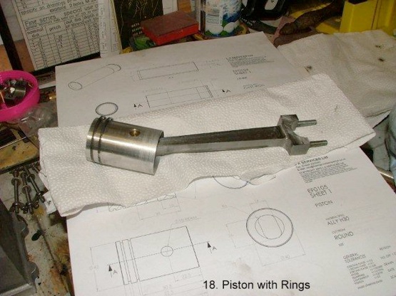
The commercial cast iron rings were carefully sprung over the piston and into position making sure they could float in the grooves with no lateral slap!
Due to the coned cylinder bore entrance at the open end, the piston would not enter with the rings, so it had to be fitted from the cylinder head end where the rings could be compressed and eased into the bore. It was then pushed to the other end so it protruded far enough to enter the rod and push through the gudgeon pin.
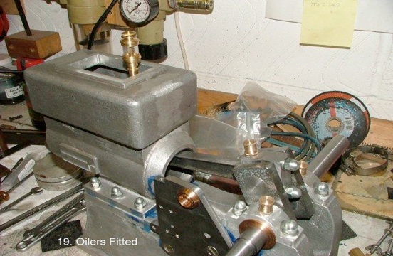
There are four oilers in all, one on the big end, one on each on the bearing caps and a drip feed oiler for the cylinder/piston. The latter was purchased from Engineers Emporium specially designed for this size engine. The other three oilers were machined from brass in two parts, the oil cups to screw into the con rod and bearing caps respectively and three knurled and threaded caps with small vent holes. Although the bearing cap oilers could have had push in covers, all three were made the same as the big end one needed screwing to prevent it being thrown out by the rotary motion of the crank!
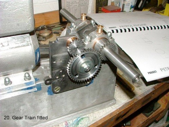
There are three gears as can be seen above, one keyed to the crankshaft driving the second gear ( 2:1 reduction) which has the exhaust cam attached, the profile of which was partly milled and filed out of ¼” unhardened gauge plate. The third gear and its shaft run in a gunmetal bearing and attached to the other end of the shaft is the governor.
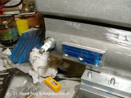
The spark plug was also purchased from the suppliers and is in fact a Japanese std. plug and is used in some of the small Honda engines. The thread is Metric with a pitch of 1mm, not a tap in my collection, so I was lucky being able to borrow one from Bruce Davey of Bruce Engineering Co, now part of Polly Engineering.
The blued area with two tapped holes is where the dummy magneto bolts on. This is a copy of the full size and fitted purely for appearance.
MEWS IS SPONSORED BY - BRISTOL EXHIBITION - HARROGATE EXHIBITION - TEE PUBLISHING - MERIDIENNE EXHIBITIONS - LYNX MODELS - CAMDEN MINIATURE STEAM - TRANSWAVE CONVERTERS - MESSE SINSHEIM - CHRONOS - PAULTHECAD.CO.UK - GLR DISTRIBUTORS - ECCENTRIC ENGINEERING - WARCO -