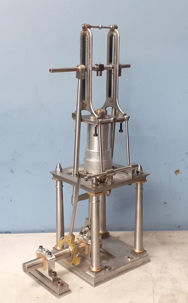
Next part is the cylinder end cover which also serves as a mount for the two cross head guides. I wanted to do this from cast iron and the most economical way was to start with a slice of iron bar.
Held in the soft jaws it was cleaned up on the OD, faced and then a 25mm spigot turned to locate in the end of the cylinder, the piston rod hole was then drilled with a 4.8mm stub drill before reaming 5mm.
Held the other way round again in the soft jaws it was faced to length before thinning down most of it to 4mm to leave a central boss which was counterbored 8mm dia for the gland and also a shallow recess turned around it for a bit of added interest and somewhere to stop the paint.
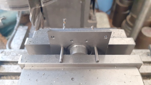
After roughly squaring up so it could easily be held in the vice jaws the centre was located and various holes drilled - four for the guides, eight for the cylinder studs and three for the gland studs.
Finally, using a couple of drill bits in suitable holes, the final 50mm square was machined and then a corner radius cutter used to add a small decorative moulding around the edge.
A start was then made on the cross head guides two pieces of over-thickness (8mm) bar were milled to 12mm width, 6mm holes drilled each end so they could be held on a mandrel and rounded over using the rotary table, and just roughing out the slots with a 6mm cutter to reduce some of the bulk so they don't take so long to bring up to soldering temperature.
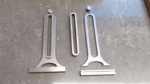
The webs were done from 3mm sheet, rough sawn they were then clamped to the CNC and the oblong slots machined. I then used a couple of top hat bushes to hold the parts to a jig plate through this slot while the outer profile was cut. I also ran a chamfer mill around what will be the outer edges to make subsequent rounding over easier. I also designed the bottom of the guides with two feet rather than a solid base as the Stuart design looks a bit bulky in this area.
A couple of lengths of 8mm square were slotted to locate onto the webs and two round bosses cut for the tie bar at the top and that is all the parts ready to solder.
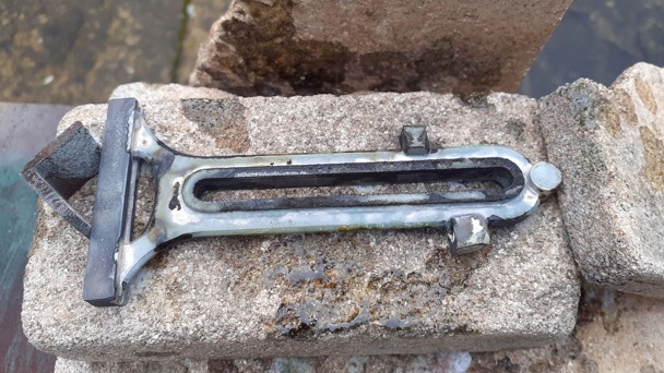
Here is one that has been soldered. I used a couple of short lengths of the slotted 8mm sq to hold the other end of the web at the correct central height.
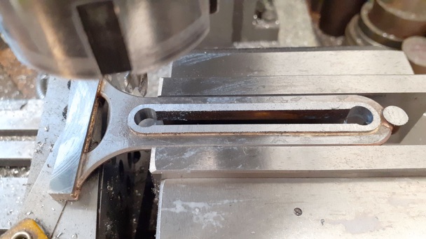
After a dip in the pickle I set the assembly up in the mill vice and took equal amounts off each side to bring the rough 8mm thickness down to the required 6mm. Then plunged the ends of the slot to 8mm dia with a 3-flute milling cutter
A 6mm cutter was then used to open up the slot to 8mm width and also machine the feet to the correct height relative to the slot. Top boss hole was also drilled relative to the slot.
Once out of the middle of the foot strip was sawn away and the two feet milled to length ready for a quick trial fit.
.Part one here Part two Part three Part four Part five Part six Part seven Part eight Part nine


