SHAND MASON FIRE ENGINE IN 1:6 SCALE
Part 1 by GUENTER KALLIES

SHAND MASON FIRE ENGINE IN 1:6 SCALE
Part 1 by GUENTER KALLIES
To give you some idea of how fire fighting may have been in the 1860s let me offer the following scenario. The night watchman calls "fire! fire!" on a misty night. Immediately the ringing fire bell wakes people up and the fire station comes to life. Two firemen run into the stable to fetch the horses and harness them up to the fire engine. At the same time another firefighter lights the boiler. Paraffin impregnated wood already lay on the boiler grate, so the fire is quickly lit. Soon the first coal was laid on the fire and, encouraged to burn via a hand-operated blower installed in the chimney.
In the meantime, the doors of the fire station were opened. The fire-fighting team sit on the box while the driver sits on the coachman's seat. Two men stand behind the machine on the footboard with one hand on the pump handrail. The engine then raced out into the night, its iron tires and the horse's hoofs rattling and sparking on the cobblestones.
In addition to this din the engine's bell soon began to clang. Sparks came out of the chimney, reflected in shining helmets and polished machine parts, a nightmarish picture to the casual observer.
By the time they reached the fire, there was already enough pressure in the boiler. The hoses were laid out and the suction tube was put into a nearby pond or other water source. The steam cocks were opened and the pump started to work. Water was directed in a high curve by the nozzle into the fire. After a short time only smoke could be seen, the blaze extinguished.
Just a few years earlier fire brigades were equipped with only a hand pump and leather bucket to fight fires and their success rate was, understandably, rather poor. The first steam fire engine was built by Braithwaite and Ericsson in London in about 1830. It was an engine with a standing boiler and a recumbent pump. The machine could pump 680 litres per minute approximately 27m high and was pulled by two horses. The weight of the machine was more than 2-tons.

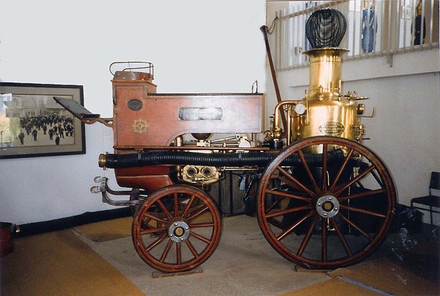
It had some similarities with the early Merryweather fire engine shown below. The 2-cylinder steam pump is recumbent on top of the front axle and works like a Worthington feed pump, directly without a crankshaft and flywheel. An original fire engine of this type from 1868 can be visited in the Fire Brigade Museum at Mulhouse, Alsace in France.

The difficulties that have had to be overcome with the introduction of steam fire engines are shown by the following anecdote: In 1859 the firefighters of New York City were worried about their jobs. Therefore, when attending a fire they first directed the hose upon the chimney of the steam engine before they started firefightlng. This was an attempt to extinguish the boiler which they viewed as a threat to their jobs. However, progress cannot be denied and five years later New York had more than 25 fire engines in service.
The development of the steam fire engine seemed to progress in odd ways at times. Thus developed a range of hand-pulled machines and also automotive steam fire engines that could move about like a street railway or a steam tractor. Also, a steam engine with a weight of more than 10,000kg was built around 1850 in the US, which was hardly ever used. More and more, the machines pulled by horses asserted themselves. These were small, efficient one or 2-cylinder machines, most of them equipped with a standing boiler.
English engineers Shand and Mason started a company in London where they began producing steam fire engines. Together they developed a very efficient, light standing boiler which could be heated up very quickly due to its high number of water tubes.

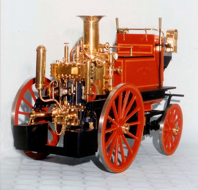
From around 1889 they produced a 2-cylinder fire engine, which serves here as a prototype for our model version. The machine was equipped with a crankshaft and two small flywheels and the movement can be observed. The steam pump is installed right behind the steam boiler which means that the tube and hose connections can be found at the back of the machine.
This fact played a determining role for the procurement of this type of machine for the Hamburg Fire Brigade in Germany. In this seaport town, a lot of goods were transported on the waterways at this time. For this reason the town had many canals, the so-called 'fleets', and many small and narrow streets terminated as dead ends because of them. With the Shand Mason one could easily go up these streets backwards and water for fire fighting could thus be pumped directly from the canal.
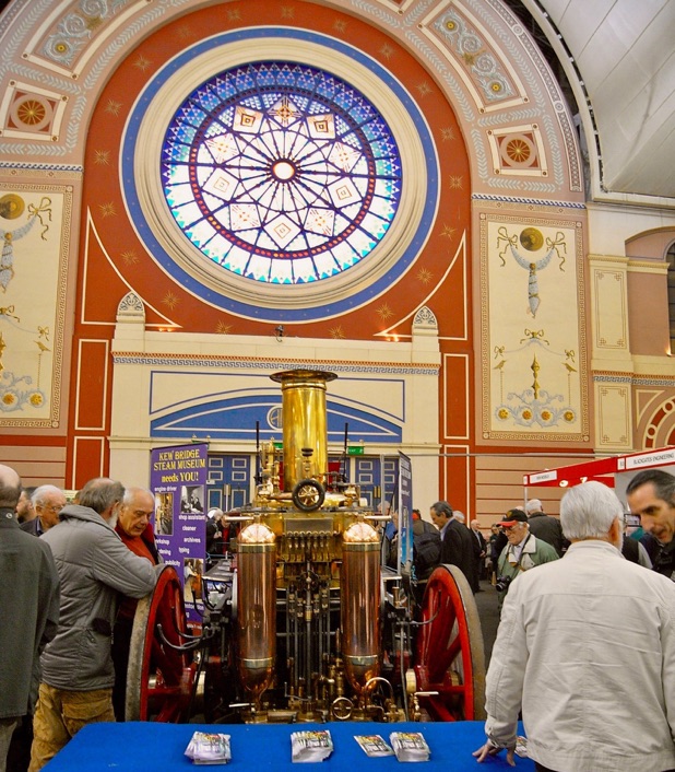
An original Shand Mason from the Southgate District Council can be viewed in London's Science Museum. This original engine was the source for hundreds of photographs and design details to produce the set of drawings accompanying these articles.

In 1967 a model steam fire engine was described in Model Engineer magazine by the well-known designer Edgar T. Westbury. He had sketched this machine, based on the Shand Mason. This version was drawn to 2in. scale (1:6) and the model came out with a total length of approximately 570mm, with a wheelbase of 290mm and
a total height of around 360 millimetres. The front wheel diameter was of 140mm, while the back wheels show a diameter of 205 millimetres.
Castings are available but the parts are rather small, and can be made without exception from stock material (e.g. brass). This alternative will avoid some of the difficulty of clamping and aligning castings in the lathe and mill.
All the components for this beautiful model were produced without exception on a very old 3.5in. Cromwell centre lathe with standard equipment. However, for some machining, access to a milling machine can be helpful.
In addition to the usual processes used in steam model construction some unusual tasks have to be done as well. For example, construction of the wooden wheels, or spinning of the boiler casing from brass. The painting and lining will also require a steady hand and perseverance. However, the model builder is also recompensed for his efforts. He will get a complete functioning machine that will attract lots of admiration.
Of course divergences from the original cannot be avoided with a functioning model of this size. However, I tried to keep these divergences as slight as possible and to limit them to hidden areas. Thus the standing boiler is copied, for example, externally exactly as per the original. However, in detail there are some divergences, mostly on the inside. As an example, the cylindrical upper portion and the tapered lower skirt of the full-size boiler is bolted together by means of two corner-shaped flange rings. Nevertheless, in the model version both these parts are firmly soldered and connected by means of a T-shaped ring.
The steam pump is fastened to this ring so that the whole machine can be removed from the chassis, including the boiler and steam pipes. This could prove helpful for servicing or for maintenance work. The boiler is provided with outside insulation and also with an authentic polished brass boiler casing. The internal construction of the boiler could not be made in prototypical fashion.
In the original Shand Mason boiler steam pressure is about 100psi. Reduced to the scale of the model the wall strengths of the boiler and tubes would become much too thin. Also, the boiler water would not be able to circulate in such thin tubes. To reach the functionality, a different construction corresponding to model size is chosen here. Also compromises are necessary with the operating controls such as the water level indicator and the safety valve. The question, to what extent the model builder wants to follow the original, is in the end a question of compromise.
The general arrangement is shown below. The construction introduced here was prepared completely using MICRO CADAM, software as used, for example, in the design of earlier Airbus aircraft.
All drawings are made very precisely with an accuracy of one hundredth of a millimetre. This gives the guarantee that everything fits well and as a result a fully functional machine can be produced.
All sub-assemblies are described step-by-step so that an interested builder can build this interesting model by himself. The less-skilled enthusiast can also make this model by following the detailed description of the working steps. Any unusual work will be described precisely. As far as jigs or tools necessary to produce the parts, they will be shown in the drawings or described in the text in detail.
However, it should be noted that building this model will take a lot of time. Off the shelf parts are not available. Every individual part must be made by hand, on the lathe or on the milling machine. Very often one must ask the questions: "How can I most simply produce this part? How do I clamp it? How do I work on it?" But this is the attraction in this hobby and satisfaction will be felt when a component or assembly is finished. Even with a construction time of one to two years it never became boring, because each single component was a new challenge.
The whole machine is split into nine sub-assemblies. Each sub-assembly has an assembly drawing and its own bill of materials from which the material data arise. The part numbers are the connection with the respective assembly drawing. The first figure of the part number gives you the information about the respective sub-assembly. Thus, e.g., the part number (425) belongs to the assembly No.4, which is the steam pump. Normally the individual parts are drawn and often the jigs and tools are shown or the production method is outlined. Next time, I will describe the chassis assembly, parts 101 to 145. The bill of material for this assembly is included in the table below.

Part one here part two part three part four part five part six part seven
Click on drawings to download - for personal use only. Although drawings reproduce well on this website, they are even better as saved downloads.

