SHAND MASON FIRE ENGINE IN 1:6 SCALE
Part 7 by GUENTER KALLIES

SHAND MASON FIRE ENGINE IN 1:6 SCALE
Part 7 by GUENTER KALLIES
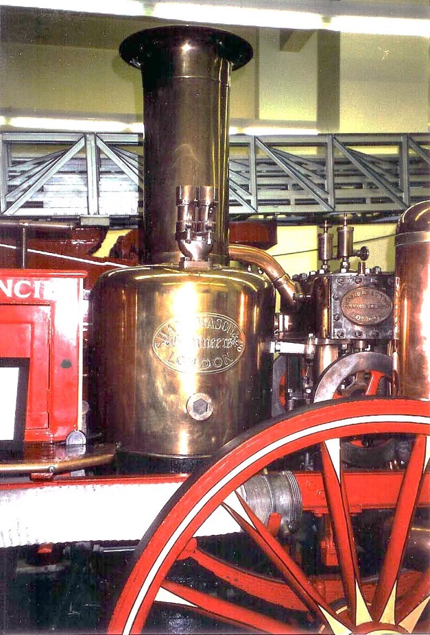
The steam boiler requires careful craftsmanship and planning. As described previously, the full-scale boiler comprised two major parts: The upper cylindrical portion and the tapered lower skirt referred to as the ‘crinoline’. They were connected by a multiple-bolted flange, which made it possible to detach the outer shell to obtain access to the internal parts. A bank of approximately 100 cross tubes were fitted to the inner firebox.


It will be generally agreed that the construction of a true scale model of such a boiler would be very difficult, and of dubious practical advantage. Most model engineers will probably prefer to follow the simplified constructional methods, now universal for locomotive and other small-scale boilers. For all, or nearly all, parts copper will be used and silver soldered together.

For the cylindrical part of the inner fire box (506) and the outer boiler shell (501) as well as for the chimney (505) suitable seamless copper tubes are available and can be cut to length. The crinoline plates (502) (507) should be cut out from 2mm copper sheets according to the development drawing. A template made temporarily from a piece of card or paper will be helpful.
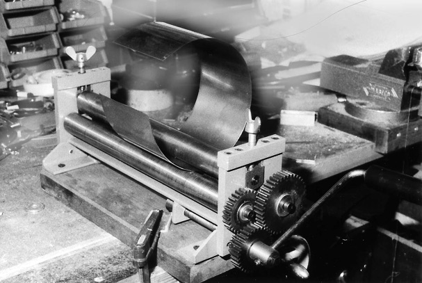
After the sheets have been bent or rolled to shape, which can be made easily in a round bending machine (photo above) or by forming around a piece of round steel with the help of a mallet to bring it in the suitable form, the joint can be made. A butt joint with a riveted and brazed 15 mm wide lap strip is recommended. The strips should be located in water space that means on part (502) to the inside, and on part (507) on the outside. Make sure that the lap strips are not installed on the full length of the crinoline in order to gives sufficient space for the foundation ring.
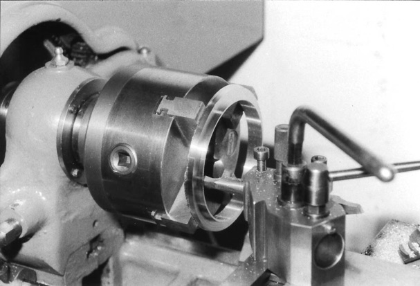
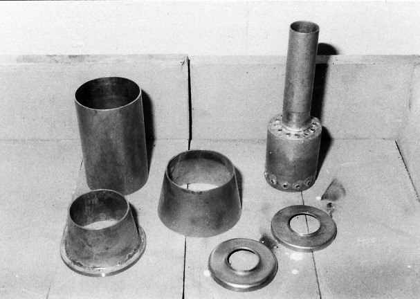
The foundation ring (515) can be made from a piece of suitable copper section bent round and brazed at the joint to a ring. For the connecting or T-ring (504) a solid gunmetal casting is recommended (photo above). Sure, a brass section bent and brazed similar to the foundation ring will do the job as well. Both parts are machined all over to final shape and drilled where necessary.
Two flanged plates are called for in the main assembly and these are of circular shape. The firebox crown plate (508) and the outer shell endplate (512) should be made from 2mm copper sheet. They can be produced by pressing with simple dies, or by spinning on wood or metal formers.
It is quite practicable to spin well-annealed 2 mm sheet copper in a small lathe as typically used in model engineering activities. The technique of spinning is well documented. The baffle plate (514) that should prevent the penetration of water in the steam pipes is made from 1 mm copper sheet in a similar way.
Let’s now assemble the inner firebox. Small copper rivets should be used to hold the individual parts in position.

The twelve bent water tubes (513) may be bent in pairs round a 34 mm dia. former. The tube should be well annealed before bending. Care should be taken to prevent the tubes from flattening; maybe a larger former with 40 mm diameter where a groove has been machined in can avoid such trouble. If all components are fitted in position they can now be silver soldered together. Silver solder with different melting temperatures should be used, so that already soldered connections are not damaged again.
Between the single soldering operations the boiler components should be pickled to remove scale. Sulphuric acid can be used, but citric acid is suited for this task and better for the environment.
The outer shell is equipped with a number of bushes (524), (525) and (526) to take boiler fittings. These should be produced either from gunmetal or from copper. Make sure that all bushes are on the right position and nothing has been forgotten. Finally the inner firebox and the outer boiler shell can be fit together and silver soldered. At the end the fire hole (503A) and the fire door frame (503) is fitted and silver soldered to the inner and outer crinoline.

For the fire hole a piece of copper pipe is brought in oval form. The fire door frame is sawed out from a piece of copper and filed to shape. The fire door frame surfaces were the door would be attached too should be machined all over. The hinge part and the locking hook should be made out of stainless steel and be fastened in suitable tapped holes.
The fire door (527) is fabricated from two parts, the door itself and the hinge tube. Both components are brazed together and then the middle part is cut out after brazing. The fire door receives a ventilating shutter (528). This is secured with a central rivet. Also these parts should be made from stainless steel. With a hinge pin of 2.5 mm diameter the flap is fastened to the flap flange.
The blast nozzle (510) is fabricated and machined from brass rod. The three single parts are silver soldered together. The union nipples (509) and (511) are turned from hexagonal brass.
Now the cold water-boiler pressure test can be made. All openings must be closed with suitable threaded plugs fitted-in with pressure tight seals. A feed pipe is connected In one of the openings. Fill the boiler with water, let air escape from the uppermost plug on the boiler. Then the hydraulic pressure can be applied with a hand pump connected to the pipe. The pressure is raised in the boiler slowly to the test pressure level of 5.5 bar (80 P.S.I.). The pressure must be maintained for at least 30 minutes. There must be no leakage or deformation. Make a test protocol in which all relevant data are exactly recorded.


The underside view of the firebox shows the fire grate (516), which is build up from eleven flat iron bars. This assembly is held together by rods, screwed nuts on both ends. Spacers are installed on the rods to keep the grate bars at the required distance.
Two brackets (517) and one eccentric latch (518) are installed on the foundation ring to keep the fire grate in position. For the attachment blind tapped holes should be used in the foundation ring to avoid risk of causing leakage. The parts (517) and (518) are made from stainless steel.

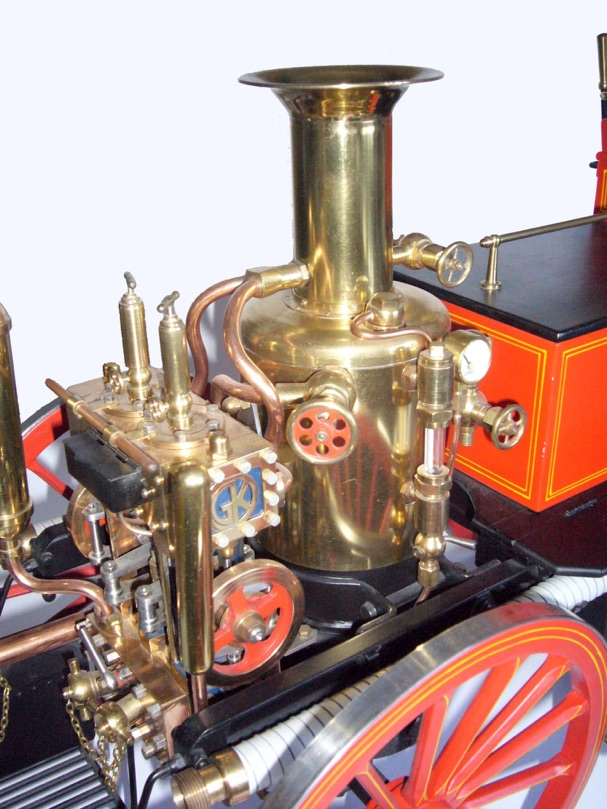
The boiler casing is brightly polished brass, characteristic of the prototype. It consists of four major parts, the jacket (519), the cap (521), the pipe (522) and the bell top (523). The jacket is intended to fit over the upper part of the boiler.
Some sort of insulating material should be installed in the gap between boiler and jacket. Half hard brass sheet metal with 0.7 mm thickness is recommended and can easily roll to the final diameter.
To transfer the accurate location of the boiler fitting holes to the jacket it is best to use a piece of clear drawing paper, which is laid around the boiler to mark the position of the holes. Use this paper as a template to transfer exactly the positions to the jacket or cap.
Two angle profiles (520) are riveted to the jacket where bolts are used to pull the edges together. A lap ring is soldered inside the top of the jacket. Its purpose is to locate the cap concentrically and flush with the outside of the jacket.
The cap (521) can be beaten to shape over a former, but the most accurate and simplest method is by spinning. A former made from hardwood, plastic material or metal can be used, chucked truly in the lathe. A soft-annealed metal disc with about 110 mm diameter is screwed to the former using a large washer and a setscrew.
With low speed and a home made tool from a piece of silver steel which is well rounded at hardened at the tip, the metal disc can be slowly shaped to the required form. Liquid soap is a good lubricant for this job. The metal must be annealed several times, so that the material is ductile.
To finish this component the joint edge and the chimney hole can be machined at the same setting. An angle section ring (521A) is fixed to the top of the cap by half a dozen small rivets.
The chimney (522) is a piece of brass pipe, which is connected with six small screws M1.4 to the angle section ring (521A).
The wide bell top (523) is another part that can best be produced by spinning. A register spigot must be provided at the base of the bell top to fit tightly inside the pipe. This may be produced as a separate part and silver soldered in position. Alternatively, the bell top can be machined completely from a casting or solid bar.
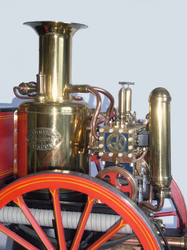
All brass parts are bright polished and should be lacquered to protect them getting tarnished. A maker’s name plate (928) made from brass can be fastened with two rivets on the RH side of the boiler casing as it is on the prototype.


Part one here part two part three part four part five part six part seven
Click on drawings to download - for personal use only.
Although drawings reproduce well on this website, they are even better as saved downloads.