SHAND MASON FIRE ENGINE IN 1:6 SCALE
Part 6 by GUENTER KALLIES

SHAND MASON FIRE ENGINE IN 1:6 SCALE
Part 6 by GUENTER KALLIES
The main steam pump
The steam pump is clearly the most important part of a steam fire engine. Precise work and a good understanding of workmanship are necessary to build this pump and get it running. Though it has not been considered practicable to design a true scale model of the full-size pump, the external shape and size have been kept as close as possible, with due regards to avoiding serious constructional difficulties.

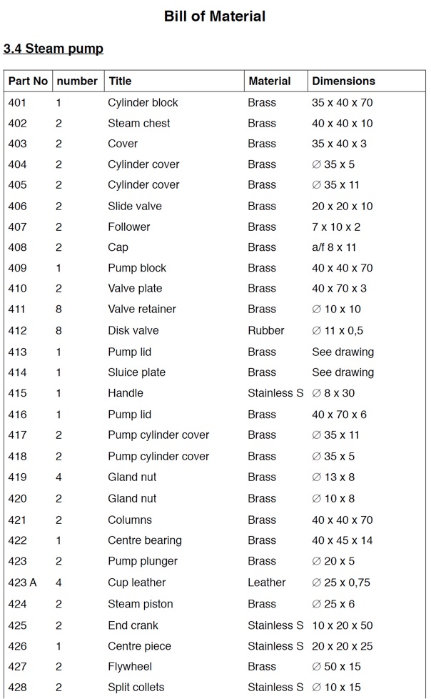
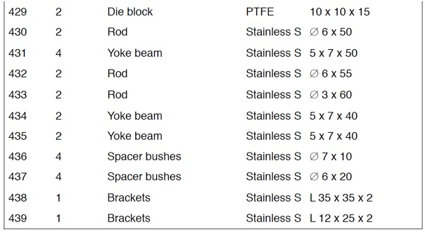
A good start on this group is the steam cylinder block (401) and the pump block (409). As already mentioned a set of 34 gunmetal castings is available. Within the set there are two gunmetal blocks to be used for the steam cylinder block or the other one for the lower pump block.

These two blocks are basically “rectangular prisms” in geometrical terms. They should be machined on all the six faces to facilitate further operation. It is, of course, possible to machine them from solid rather than castings. A bronze or brass block machined square all over to the external dimensions can be used. Then the pockets in the front and back can be milled out. These will later be filled with insulating material to keep up the temperature inside the cylinder.
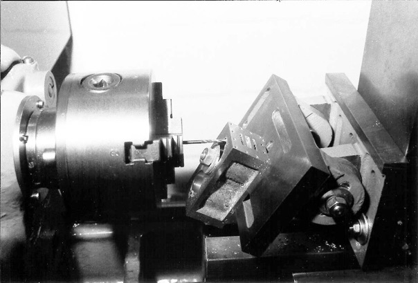
We start with precise marking and boring one hole into the steam cylinder and the pump block. The location of the centres in both the steam cylinder and pump blocks must be set as accurately as possible to ensure true alignment when the parts are assembled. It is, therefore, worthwhile to make a simple machining jig. This jig consists of a plug of 19 mm diameter, bolted to the faceplate. This fits closely in the already drilled first pump block hole. In addition a strip of metal should be bolted to the faceplate as a reference for the block alignment.
Now the second hole in the pump block can be made. Slide a sleeve with 19 mm inner and 22 mm outer diameter over the plug and install the steam cylinder block to this arrangement. Now the second cylinder hole can be drilled. Working this way will make sure that all the four holes in the steam cylinder and the pump block will be perfect aligned. Identification marks on each part are helpful for subsequent assembly to make sure that all the components are in the correct relation to each other.
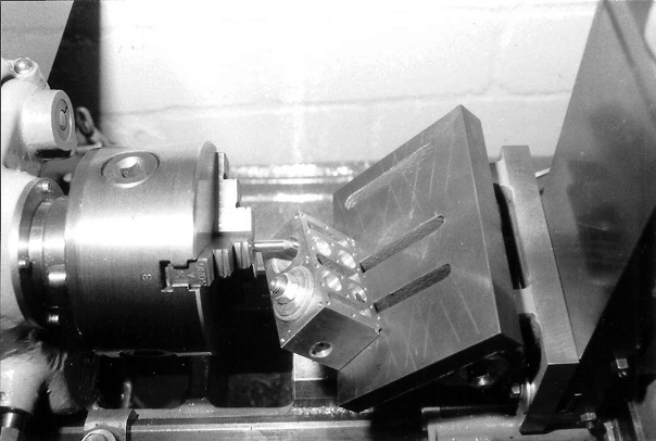
Before finishing the cylinder bores by lapping or honing (see photo below), the other operations including port cutting, drilling and tapping may be carried out. To drill the steam passages of the cylinder block or the water passages of the pump block a simple support block may be made in either wood or metal, on which the block may rest for drilling.
Different blocks with different angles are needed. A 30° angle is specified for the steam cylinder while 45° is needed for the pump block. Always check the angle on the actual job it may differ slightly on yours. It is recommended to fit a mandrel into the bore, so that the drill has guidance.
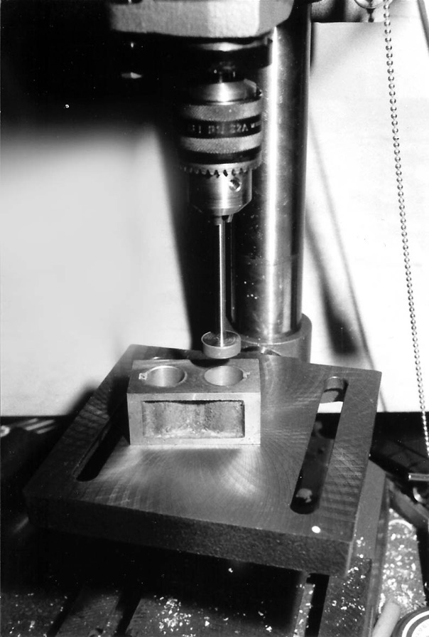
Finally, the bores should be lapped or otherwise finished. The use of a copper or an aluminum lap is recommended. For working on bronze or gunmetal, it is not advisable to apply harsh abrasives. The use of a metal polish cream and a drop of oil will work successfully. A few minutes on the drilling machine with moderate speed is all that is needed.

The steam chest (402) and the accompanying cover (403) can be made from gunmetal or brass. The attachment holes must fit with those of the cylinder (401). This can be achieved easily by using the steam chest as a drilling jig. The steam chest cover offers the possibility to take up the initials of the builder. If these letters sawed out from 1 mm brass sheet metal, they can be simply soldered in the pocket of the cover. Here again, identification marks will be helpful for later assembly.

The cylinder covers (404) and (405) should have a close fitting concentric register spigot. On the lower cover it is important that the gland boss and bore is exactly central to ensure alignment of piston rod.
The slide valve (406) is machined from a piece of bronze or brass. The length and the 2 mm slot are important. The follower (407) should have a close fit to the slot of the slide valve. The cap (408) is simply turned from 8 mm hexagonal stock.


The inlet and discharge valves are fitted to a valve plate (410). The plates made from brass are identical except for the apertures. This are needed in the suction valve plate (the rear one) only. The location must meet the inlet passage in the pump block (409). The disc valve (412) is punched out from thin rubber. The valve retainer (411) turned from brass and provided with a screwdriver slit. It is important that the disk valve can lie flat on the valve plate surface without deformation.


The pump lids (413) or (416) form the inlet and discharge valve chambers. The two lids can be either made from castings or machined from a piece of brass. The position of the holes for fixing them should match with the valve Plate (410), which should be used as a jig to locate the holes in the pump lids but also in the pump block (409). The discharge side lid may be fitted with one or two outlets as fitted to full-sized. One is sufficient for practical demonstration of the model. However, for twin outlets, it is necessary to make separate union components, with stems to fit tightly in holes drilled apart at angles of 15° on each side of the plate center, and silver-solder them in. The two bosses as shown in the drawing should be silver soldered at the same time to the discharge lid. One of the bosses is for the sluice plate spindle, which allows cutting off one ore other of the outlets, while the flange plate on the top face is for the connection of the main air vessel (739)
The projecting ends of the twin should be trimmed flush with the inside surface of the discharge pump lid. Here the sluice plate will be assembled and therefore a smooth surface is needed. The sluice plate (414) and the handle (415) are best made from stainless steel to avoid corrosion. The sluice plate and shaft can either riveted together or brazed. The square hole in the handle can worked out using a small needle file. This job is a somewhat tricky but it works.
The pump cylinder covers (417) (418) are made in the same way as those of the steam cylinders, and the outer edges of their flanges should be turned to the same diameter as the latter. In the case of the upper cover, the register spigot and the center hole should be carried out at the same setting, to ensure concentricity.
For the gland nuts (419) and (420) a suitable piece of round brass should be provided first with the longitudinal slots on the outside. The drilling, counter boring and tapping of the gland nut are straightforward operation, calling only for normal care in maintaining concentricity and usual alignment.

Now it becomes exciting. The pair of columns (421) can be made in one piece, with essential machining carried out before cutting it in two portions. Starting with a piece of brass milled down to 38 mm x 38 mm. This may be held in the four-jaw chuck or clamped to the faceplate. Now, turn the inside and outside surface to final shape. Next step is the cross drilling of 12 mm and machining or filing the square holes in the column. After silver soldering the bearing bush, which should be drilled slightly smaller then the final diameter, say 7.8 mm, the whole thing can be cut into two portions. Machining the saw cut surface, trimming the bush to length and drill and ream the bearing bush to final dimension would finish the job. Perhaps it makes sense to assemble the columns with the steam cylinder and pump blocks for this drilling and reaming operation to ensure perfect alignment in the assembled condition.

The centre bearing (422) again can be made from a suitable casting or it can be fabricated by brazing or even machined from the solid. Whatever method of making is selected, a split centre bearing is necessary. Therefore, the cap (422A) should be a separate piece of material, which is temporarily soft soldered in place. The split line is now the reference for cross drilling and for the bearing.
Machining and filing the component according to drawing will finish this part. A final check on alignment of the three bearings should be made by threading them on a straight, close-fitting bar, and resting them on a surface plate or other flat surface. It is possible to adjust any discrepancy by scraping the base seating of the pedestal, or fitting shims under them.
The pump plungers (423) are each made in two parts and two “cup leathers” (423A) are clamped in between. These are the classical design for plungers and have long been favoured for hydraulic packing. Sure in the small scale of a model engine a single piston turned from solid plastic material like nylon or P.T.F.E. can be used. The steam pistons (424) should be turned, grooved, drilled and counter-bored at one setting from a piece of bronze or brass.
In order to avoid excessive shaft length, and so keep as close as possible to the proportions of the prototype, the flywheels and eccentrics have been made integral with each other. The flywheels (427) are most easily made from a casting, but it could be made from the solid, or fabricated by brazing. The flywheel is held in the chuck, over the outer rim, as truly as possible, for drilling and taper boring the center hole. It is important that the taper should match that of the collets (428) in each case.
The flywheel is offset to a radius of 3 mm for machining the eccentric surface. The flywheel may now be mounted on a taper mandrel for machining the rim, crown and boss face.

The method of securing the flywheel using split collets (428) is not common for steam engines. However, these allow easy adjustment and provide adequate securing without the need for keying. Each collet can be machined at one setting, by first drilling and boring centrally, and then turning the external taper to fit the flywheel. The pair of collets may be made on the two ends of a piece of steel bar, stainless steel is recommended. The collets should not be parted off until they have been saw cut endwise for their full length.
There are practical reasons to specify a plastic material for the die block (429). Teflon or nylon promote quiet operation and will work for long periods even with no lubrication. The material can easily be machined and the component should be finished to a close sliding fit to the yokes.

The crankshaft for the steam pump is of unorthodox design and construction. It consisted of three separate parts; the two end cranks (425) and one centre piece (426). While it is not impossible to make the crankshaft in one piece, one disadvantage is that the die blocks would need to be split.
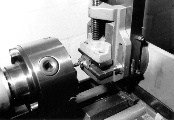
The crankshaft components can be made from suitable pieces of steel. Again stainless steel is recommended although mild steel could be used. After marking out and sawing away most of the unwanted metal, each of the parts may be set up in the four-jaw chuck or on an angle plate mounted on the faceplate for turning. A simple fixture for machining the crankpins is proposed and shown on the drawing above.

All of the individual parts for the piston rods and yokes should be made without exception out of stainless steel. The profile for the yoke beams (431) or (434 and (435) should be machined on a suitable 5 mm sheet metal. Then 7 mm wide strips can be separated, which must be drilled, tapped and rounded at the ends. Care should be taken to mark out and drill the holes as accurately as possible, also to tap them squarely so that they will fit truly on the rods. The accompanying piston or valve rods (430) (432) and (433) are screwed to the yokes and sweated in addition to produce a permanent assembly.

The spacer bushes (436 and (437) are also best made out of stainless steel. Maintaining the same length of the corresponding parts is most important to ensure parallel assembly of the yokes, otherwise the alignment of the pistons and plungers will be affected when the complete rod system is assembled.
The last parts of this assembly are the attachment brackets (438) (439) with which the complete steam pump is attached to the boiler. These parts can be made best by sawing out from a piece of square pipe 40 x 40 x 2 mm, which is commercially available and can be found, sometimes, in a scrap box.
Again, stainless steel is recommended for these components but mild steel will do the job as well. Alternatively, the brackets can be cut out and formed from sheet metal and bent to shape, but in this case care should be taken with the sharp bending to avoid cracks. The position of attachment holes should be carefully checked with the counterpart, the steam pump or the support ring on the boiler respectively.
The components should be assembled using model hexagon bolts. These screws should have a smaller head width, but a bigger head height that will looks much more realistic on a model. Rustproof screws made from brass or stainless steel is the better choice. The back-sided pump lid (416) is fastened with M3 countersunk screws.
For the cylinder front and rear cover plate 0.7 mm sheet metal is recommended, and are fastened to the cylinder block using some short M1,4 screws.
Care must be taken with assembly of the components. All joints of the cylinder block or pump block must be steam or water tight. Make sure that the joint surfaces are flat and even, possibly finished by lapping. To seal the joints thin gaskets made from oiled paper can be use or you may decide to use sealing compound which is available from specialized trade suppliers.
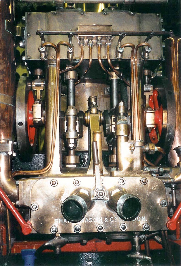
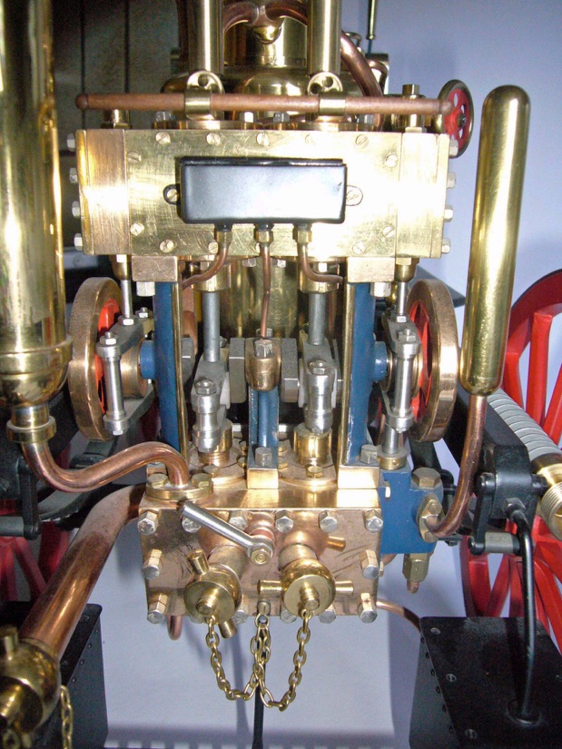
The classical way to seal the piston and valve rod glands is to use soft packing; graphite yarn for the steam glands and tallow-cotton for the water glands. It is best to form it into rings or “grommets” before insertion. However, O-rings are very popular today and readily available in various sizes as an alternative. Photos below show the model steam pump...
Click on drawings to download - for personal use only.
Although drawings reproduce well on this website, they are even better as saved downloads.