The standard exhaust position comes too close to the conrod if taken straight out and there is not much room to put a bend into the pipe so with the ‘solid’ valve chest temporarily screwed into place a recess for a round boss could be positioned further from the cylinder centre line to clear the conrod.
After assembling the chest and a bit of rod with JBWeld and allowing to set the boss was milled back to length, M1.6 stud holes added for the exhaust pipe flange and then after tilting the casting an angled hole was drilled to meet the central port.
Even though I'm unlikely to use them I drilled and tapped for drain cocks and spot face around the holes.
Last job on the cylinder was to turn a couple of decorative bands which were then cut and JBWelded to the outside of the cylinder to add a bit of interest as I did not intend to fit wood cladding.
I made the crosshead slippers about 50mm longer than the Stuart drawings show to help with smooth running and added a half round cut out each end for decoration more than reducing the reciprocating weight using a couple of plunges of a 6mm cutter.
Rather than have integral spacing bosses I turned up two steel sleeves to fit between the pivot on the end of the piston rod and the back of the slippers.
Then I took equal amounts of either side until the slippers were a nice running fit inside the guides.
The last bit for the upper part of the engine was the spacer rod that holds the tops of the two guide ‘castings’ apart, I added a bit more decoration to this as the plain rod on the drawing was not that special. Again I am using a small hollow sleeve on the threaded end spigot so I can use tailstock support without the need to drill a centre hole.
The piston was faced and skimmed clean from some 1in. stock, drilled 3mm deep x 4mm dia for the reduced end of the 5mm stainless steel piston rod and then tapped M4 the rest of the way through. After parting off it was held the other way round, faced to length and a recess cut to accommodate a lock nut.
Then holding by the rod in a collet and using tailstock support in a small centre drilled hole in the end of the rod the piston was turned to diameter. Ring groove was cut, and I added a small V-shaped oil groove. The piston won't be taken off the rod after this to ensure it stays as concentric as possible.
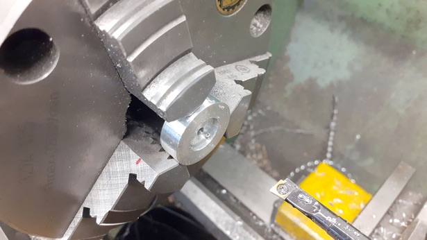
I needed a couple of oil cups for the main bearings so some 1/4" brass had a 4mm spigot turned on the end which was then threaded M4 x 0.5 fine and then transferred to the spin indexer to cut a hexagon.
A bit of file and emery work soon had the bottom of the cup shaped ready to be parted off.
With the part finished cup screwed into a threaded holder a 4mm ball nose cutter was used to cut the inside profile and then the oil hole drilled through 1.2mm.
While the brass bar was out I made a simple form tool for some drain cock bodies by milling some 9mm dia silver steel to half thickness and then used a 6mm cutter to form a 2mm deep recess in the end. The edges either side were riled round and the tool used as it was to shape a couple of valves.
The flange to the right was then machined to a hexagon, just like the oil cups, and the one on the right reduced to 4mm before parting off, As I'm not likely to run mine on steam I just added dummy handles that were taper turned from 2mm stainless and bent to shape before being Loctited into place.
Well that’s about it! Next time we can see what it looks like with a coat of paint, and how it runs.
.Part one here Part two Part three Part four Part five Part six Part seven Part eight Part nine Part ten Part 11 Part 12