Well, I thought that I should at least use one Stuart casting otherwise it would not really be a version of the James Coombes, so Santa gave me a cylinder casting to modify.
You quite often see the comment that today’s Stuart castings are not as good as the old ones but from what I have used over the last few years they have all been fine, this was no exception. Small amount of thin flash and a bit of material where the iron was poured; better to have that proud than over-fettled and cutting into the surface.
Couple of minutes with files and it cleaned up nice enough and ready to machine.
I used the method that I came up with on the Real to machine the cylinder to ensure the bore, piston rod end and port face are all square to each other. Firstly packing up the vice on the lathe cross slide and then further packing the casting in the vice using feeler gauges to get the centre line of the bore to the required height. You can also see I have thin strips of aluminium between the jaws and the casting so I get a good grip on the cast surface,
When setting up, ensure some of the piston rod end of the casting is protruding beyond the vice jaws. Finally use an edge finder in the tailstock to set the casting central to the lathe axis and lock the cross slide.
Machining starts with a between centres boring bar, three passes were enough to get to size; in this case I went with 25mm on the metric version.
Next the top end of the cylinder can be fly cut down to the final size.
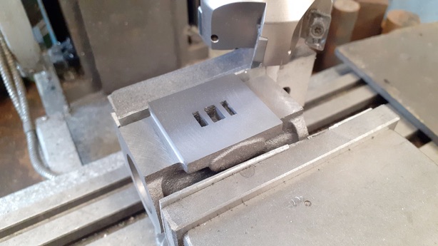
Now WITHOUT removing the work from the vice transfer to the mill and the port face can be machined ensuring it is true to the surfaces machined on the lathe. I also used the face mill to clean up the two flat areas either side of the port face, their 0.8mm tip radius leaving a nice fillet in the internal corners.
Changing to a 3-flute milling cutter the other edges of the port face were cleaned up. happy to say that the cast-in ports were very crisp and even, so needed no further work.
The last job while things are set up is to drill and tap the holes for the studs that retain the valve chest and its cover.
The cylinder can then be held with the machined end facing down and the other end milled to bring the casting to final length and while it's like that may as well tap for the stud holes. The ports were a tiny bit off from centre at the ends so the stud holes just ran into them but not a problem and would not have affected things with the smaller number of studs used on the Stuart design.
I'd been contemplating how to deal with the inlet and exhaust on this engine while waiting for the cylinder casting to arrive and once I had offered it up to the rough assembled engine decided on a plan of attack.
First I needed a valve chest, so machined up a suitably sized rectangular block and, and at the same time, a thinner one for the chest cover. I located the centre of where the valve rod would go on the mill and drilled a small centre hole then set this to run true in the 4-jaw chuck. Then it was just a case of drilling 2.5mm for the valve rod, counterboring 5mm for the gland and turning a spigot to form a round neck as I wanted to use round rather than oval glands on this.
Part of my modified design was to make it look like the valve chest was an integral part of the cylinder casting which is quite common on full size it is just a lot of models have them separate to make it easier to machine the flat port face. So I drilled and counterbored each corner for M3 cap head screws to hold the chest to the cylinder and tapped the rest for studs. In the next photo I have mostly completed stitch drilling out the waste using a stub length, split point 6mm drill at 5mm stepover. As you can see the holes link together, don't wander, and there is no need to spot drill first.
One more hole and the waste drops out without any hammering or sawing to link the holes.
The cavity was then cleaned up with a 4mm cutter, try not to get carried away at the ends of the cut.
With the vice stop in place it was easy to position the cover and drill to the same pattern, the recess was cut with a 4mm dia cutter with 1mm corner radius to 1mm deep.
.Part one here Part two Part three Part four Part five Part six Part seven Part eight Part nine Part ten Part 11