Started work on the work table by opening up the four 3mm holes to 4mm and countersinking them.
I made sure that I countersank enough so that the head of the bolt will remain under the level of the table.
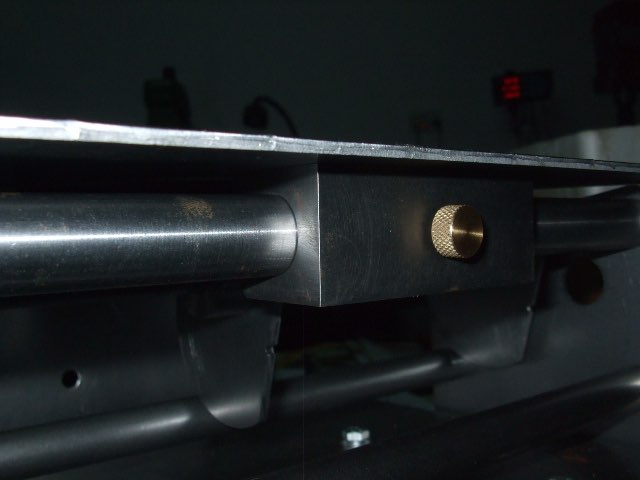
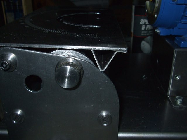
The table bolted up to the cast iron sliding block. The brass screw is the locking screw.
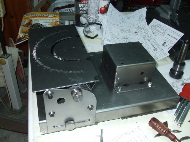
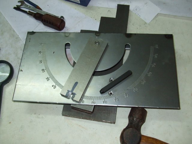
Table in position. Starting to take shape.
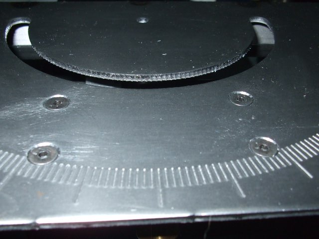
I managed to punch the numbers with the aid of a jig.
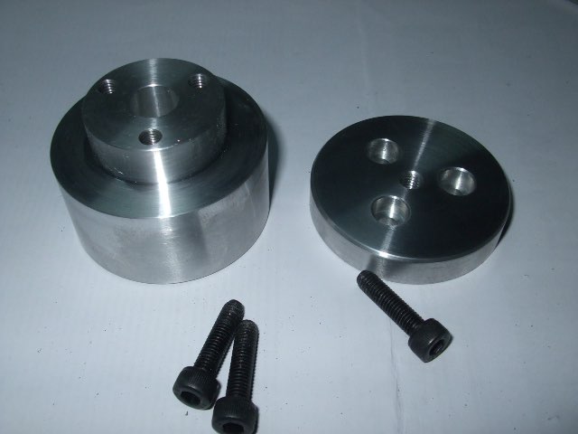
The wheel hub and clamp were made with the supplied aluminium blanks. There isn't a lot of extra bar stock available so I had to be extra careful. Started by facing both blanks by taking off as little as possible. Ended with only 3mm extra. Not a lot.
I then made an 11mm plug gauge for the hole in the hub as per instructions. I then put the clamping washer in the chuck and drilled and reamed a 5mm hole. Later on this will be tapped 6mm.
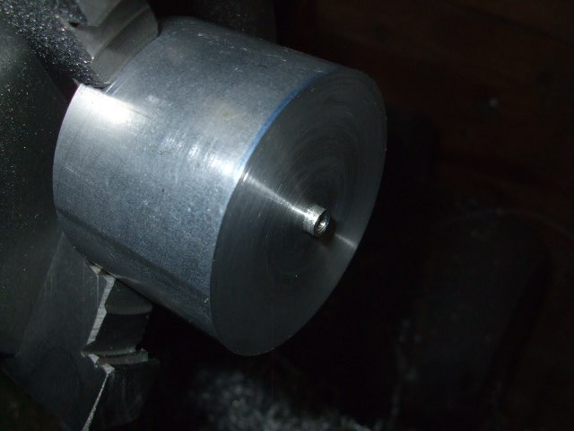
Put the hub in the lathe and drilled and tapped 4mm and then made a 2.5mm spigot of the same diameter as the hole I just made in the washer.
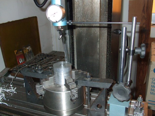
Bolted the washer to the hub and transferred it to the mill. After locating the hub under the spindle with a coaxial indicator.
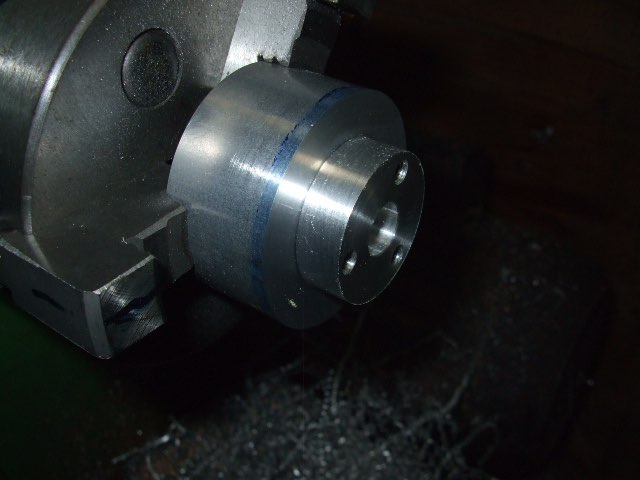
I proceeded to drill three holes using the DRO Bolt Function through both the washer and the hub. Washer removed and the three holes tapped 5mm.
Decided to bore the 11mm hole on the lathe as I can do all the operations in one setup and so keep everything concentric.
I reamed the 6mm hole in the table and I also managed to get the -2deg tilt of the table. Had to file/grind the curved part of the side plates to make the table go a bit lower.
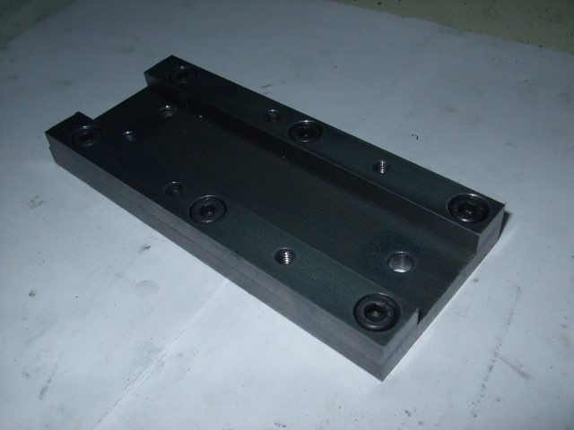
Started the toolholder with the sliding base. Basically a base with two guide bars on the sides with lots of holes in it.
I located all the holes by measurements from the plans. I nearly missed it but was lucky I noticed it before drilling; the six counterbored 5mm holes in the guides are a bit larger than usual for a 5mm bolt. In fact the through hole is 5.5mm and the counterbore is 9.5mm. I guess they are larger than usual to give some leeway in adjusting the guides. What I found strange is that there is another 5mm through hole through both guides and the base which is not that wide. I drilled it 5.2mm as per plan and I can always open it up if required later on. Also I found a minor mistake in the location of this particular hole. On the plans it is saying 2.75" from the front of the base of the toolholder. When I calculated it I found that it should be 2.74". The supplier was advised and the plans have been amended.
Part one here Part two Part three Part four Part five Part six Part seven Part eight Nine 10 11 12 13 14